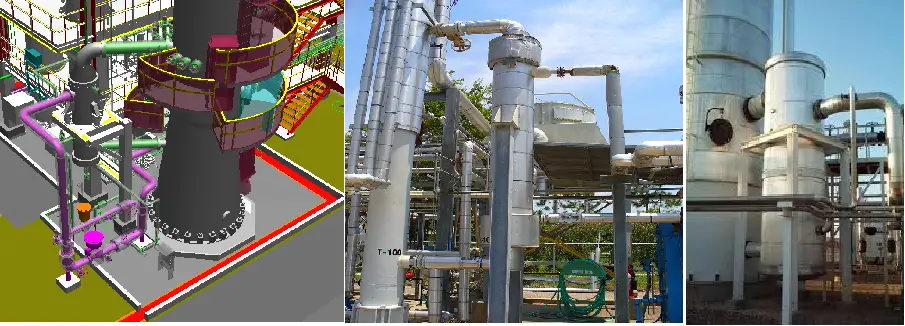
Vertical Reboilers play a significant role in the Process industry. Reboilers are a type of Heat exchanger that is used for heating the bottom fluid of industrial Distillation columns. Normally heat from steam (or any other high-temperature fluid) is utilized to boil the liquid from the bottom of a Distillation Column. Normally this heating effect generates vapor which is then returned back to the Column at a higher elevation to drive the distillation separation.
The piping arrangement between the distillation column and reboiler for this action is normally very stiff and requires careful Analysis to keep the column and Reboiler nozzle loadings within an acceptable limit. The following article will provide the Stress analysis methodology of a vertical Reboiler connected piping system using the software tool Caesar II, developed by Coade Inc.
Applicable codes and standards for Reboiler Piping Stress Analysis
ASME B 31.3-Process Piping,
ASME Section VIII-Pressure Vessel design (Normally distillation columns and reboilers are manufactured based on these codes),
Column and Reboiler allowable nozzle Loads (Should be taken from Equipment Vendor in case no standard Project-specific load is not available)
Temperature Profile for Modeling the Rebolier and Column
Column Temperature
In the absence of project-specific guidelines, the Operating/ Design temperature of the Column shall be considered the same as the average operating/design temperature of the column outlet piping attached to each draw-off nozzle
Reboiler Temperature
The Reboiler modeling uses the following information in the absence of project-specific guidelines:
Tube side Inlet Temperature = bottom (outlet) Piping temperature of the tower.
The temperature of the tube = average temperature between tube inlet and outlet piping.
Tube side outlet temperature = temperature of the tower inlet piping.
If the temperature of the Column inlet piping (channel outlet) is not known, consider the reboiler tube outlet temperature as mentioned in the vendor drawing or confirm from the process engineer.
Shell side temperature = average of the Shell inlet (Normally Steam) and outlet piping (Normally Condensate).
Modeling of the Reboiler with an Expansion joint in Caesar II
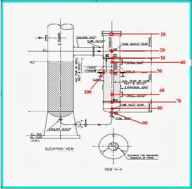
Initially model the reboiler as a rigid body following the below-mentioned steps. Refer attached drawing (Fig. 1) as a reference:
1. Model nodes 10-20 and 20-30 with tube outlet temperature and pressure considering channel material, diameter, thickness, length, and fluid density (Also include insulation thickness and density if any) from Rebolier General Arrangement (Henceforth called GA) drawing.
2. Model nodes 30-40, 40-50, and 60-70 with shell average temperature and shell design pressure considering shell material and dimensions as mentioned in reboiler GA.
3. Model element 30-70 with Channelside average temperature and design pressure taking tube material, shell diameter, and thickness from GA drawing.
4. Model 70-80 and 80-90 with tube inlet temperature and pressure considering channel material, diameter, thickness, and length.
Fig. 1: Reboiler piping schematic diagram for modeling in Caesar II
5. Model elements 50-100 with shell-side properties and model the support restraint at node 100. Similarly model all other support elements as required from the GA drawing (check 2 lugs, 3 lugs or 4 lugs supported system).
6. Now make the elements 10-20, 20-30, and 70-80 as flexible (i.e, non-rigid)
7. Check the total operating weight of the reboiler from GA (if operating weight is not available assume 70% of water-filled weight) and the weight already considered in elements mentioned in step no 6 (considering fluid and insulation; you can do it easily by clicking the single run button in caesar II). Provide the remaining balance weight in rigid element 30-70 (tube weight). Recheck once again by clicking the single run button to ensure the actual weight in the caesar model matches the weight provided in GA.
In case there is no expansion joint in the shell, model element 30-70 with shell-side average temperature. Rest all other parameters will remain the same.
As you are planning for reboiler piping I am sure you know the modeling of the column and attached piping. So I am not describing it. So model the column and attached piping to make a complete system as shown in the attached figure (Fig. 1).
Supporting Arrangement for Vertical Reboiler Piping
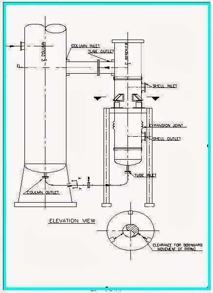
Reboilers may be supported by the column or by making an independent structure. In both of cases, there is a possibility to support the reboiler lugs directly on the structure or there may be a requirement for spring hangers (bottom mounted). Sometimes Slot holes and PTFE/graphite sliding plates are required to reduce frictional effects. So this information needs to be informed to the equipment vendor. Location of the lugs to be fixed in such a manner with respect to nozzles, bellows, and other accessories to avoid fouling, etc. If the reboiler is supported on spring supports (See attached figure Fig. 2) then the following points need to be considered:
Cold/Hot Load Conditions should be the same for all the springs
Spring should be designed keeping in consideration the empty weight of the reboiler in case of standby and steam out condition.
Slotted Holes are not required on the lug of reboiler in case of spring support
Fig. 2 : Supporting Arrangement of Vertical Reboiler Piping using Spring hangers
Mirror polished SS plates/PTFE plates if required are to be provided by the vendor
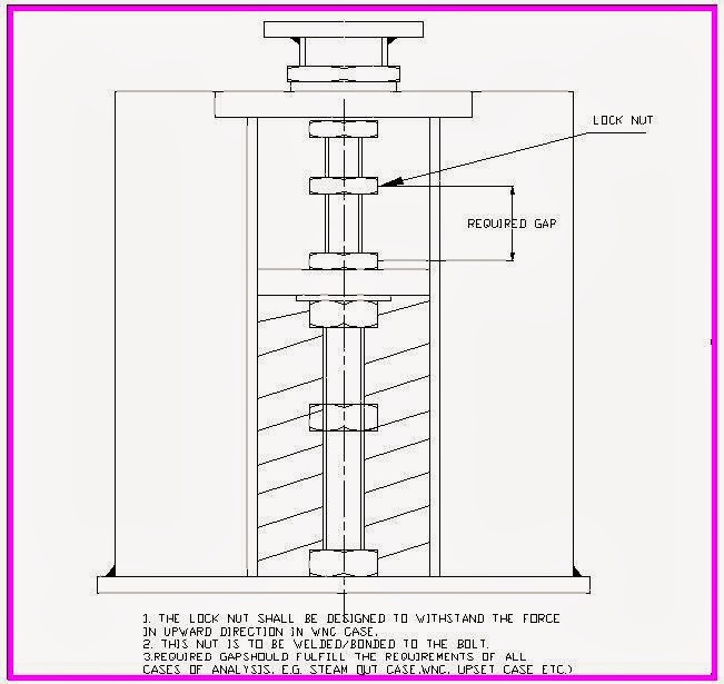
If the loads on nozzle are quite large because of the back force due to spring in WNC Case, the Lock Nut (Refer above figure) can be provided on spring to act as the limit stop.
The required gap shall be input in Caesar as a gap on restraint applied at spring in (negative Y) Direction.
The pipe stress Engineer has to provide details of the Lock Nut (See the figure attached below, Fig 3) and the loads on the nut in the Spring Datasheet.
Fig. 3: Locknut arrangement for Reboiler Piping Supporting
Load cases for Reboiler Piping analysis
Load cases are to be prepared based on operation possibility. So one must consult with the process engineer to know all the possible load cases. Normal possibilities are mentioned below:
1. Operating temperature load cases (W+P1+T1)
2. Design temperature load cases (W+P1+T2)
3. Steam out temperature load cases (W+P1+T3)
4. Upset Condition load cases (W+P1+T4): This condition may arise if the fluid is flowing in one part of the reboiler and no fluid is flowing through the other. Normally during start-up, these types of cases may appear. Sometimes it may happen that you have to first heat the reboiler shell before you can start the flow of process fluid through the tubes. Consultation must be done with the process engineer while creating all such load cases.
5. Sustained load cases (W+P1)
6. Prepare all occasional and expansion load cases as per normal project procedures. It is sometimes required that two or three reboilers of similar type are connected to the same column. In this case, some reboiler may be in standby condition. So that situation is also required to be interpreted while making load cases. So additional load cases need to be added accordingly.
Few Important Notes related to Re-boiler Piping Stress Analysis
Reboiler column circuits being one of the most critical systems from a stress analysis point of view one should take extreme care while analyzing such systems. The following notes will help the stress engineer to take an engineering judgment:
1)All of the junctions between the shell & nozzle can be considered as reinforced after confirmation from the Mechanical Department
2)If nozzle loads exceed the allowable, loads should be forwarded to mechanical for further evaluation. Alternatively, the stress engineer has to perform WRC or FEA to qualify the nozzle loads. It is better to forward the WRC/FEA output results to Mechanical for their review.
3)Nozzle loads should be checked thoroughly with the spring setting when the reboiler is on standby during steam out.
4)Flange leakage evaluation should be performed as per client requirement and the rating of flanges should be changed if required, and the same information should be forwarded to the Mechanical and Process Team.
5)Initially, the Nozzle loads are to be forwarded to mechanical as three times the project-specific pressure vessel loads in Caesar to take care of the upset conditions.
6) The requirement of Spring supports, PTFE/SS plates, Slot holes, Locknut arrangement, etc. is to be marked in the Engineering drawing for incorporation into the final vendor drawing.
7) Location of lug to be fixed in such a manner with respect to nozzles, bellows, and other accessories to avoid fouling, etc.
8) Fouling of the Reboiler Nozzle (Shell Outlet) with structure should be checked.
I am a Mechanical Engineer turned into a Piping Engineer. Currently, I work in a reputed MNC as a Senior Piping Stress Engineer. I am very much passionate about blogging and always tried to do unique things. This website is my first venture into the world of blogging with the aim of connecting with other piping engineers around the world.
6 thoughts on “Stress Analysis of Vertical Reboiler Piping using Caesar II”
Please provide guideline or method for analysis of piggable line including pig receiver launcher.
Images are already there… Are you opening the article in any one of the following browsers? Chrome, Mozilla, or Microsoft Edge. Please try with any one of the above browsers. There is some display problem with internet explorer. So images may not be visible.
OK. Thank you. I Opened with another browser and It is OK.
Do you have more detail about vertical reboiler on SPRING hanger? FIG . 2
You wrote that :
Slotted Holes are not required on the lug of reboiler in case of spring support
then how the reboiler is supported?
Hi, I have below queries in modeling the vertical reboiler:
1) As you wrote in point “2. Model node 30-40, 40-50 and 60-70 with shell average temperature” what about the element from 50-60 as it seems missing. Please correct me if I am wrong.
2) How the effect of expansion joints are considered in modeling.
3) The spring supports are required where there is a differential thermal expansion between the column and reboiler. Please correct me if I am wrong.
4) Will the location of expansion joints (i.e.) above or below the lug support will alter the modeling procedure instructed by you. As in your model the expansion joint is below the lug support.
Dynamic Pipe Stress Analysis is a specialized engineering evaluation used to assess how piping systems respond to time-dependent (dynamic) loads, such as:
Seismic activity (earthquakes)
Water...
In the piping engineering industry, the terms FIV, AIV, and Random-Vibrations refer to different types of vibration phenomena that can affect the integrity and safety of piping systems. In recent...


")


Please provide guideline or method for analysis of piggable line including pig receiver launcher.
Hello Anup
This article is useful, but I can’t see the figures. Would you please send a right copy to me.
https://whatispiping.com/stress-analysis-of-vertical-reboiler-piping
Regards
Ali
Images are already there… Are you opening the article in any one of the following browsers? Chrome, Mozilla, or Microsoft Edge. Please try with any one of the above browsers. There is some display problem with internet explorer. So images may not be visible.
OK. Thank you. I Opened with another browser and It is OK.
Do you have more detail about vertical reboiler on SPRING hanger? FIG . 2
You wrote that :
Slotted Holes are not required on the lug of reboiler in case of spring support
then how the reboiler is supported?
Hi, I have below queries in modeling the vertical reboiler:
1) As you wrote in point “2. Model node 30-40, 40-50 and 60-70 with shell average temperature” what about the element from 50-60 as it seems missing. Please correct me if I am wrong.
2) How the effect of expansion joints are considered in modeling.
3) The spring supports are required where there is a differential thermal expansion between the column and reboiler. Please correct me if I am wrong.
4) Will the location of expansion joints (i.e.) above or below the lug support will alter the modeling procedure instructed by you. As in your model the expansion joint is below the lug support.
how to decide the weight of reboiled? full or empty?