
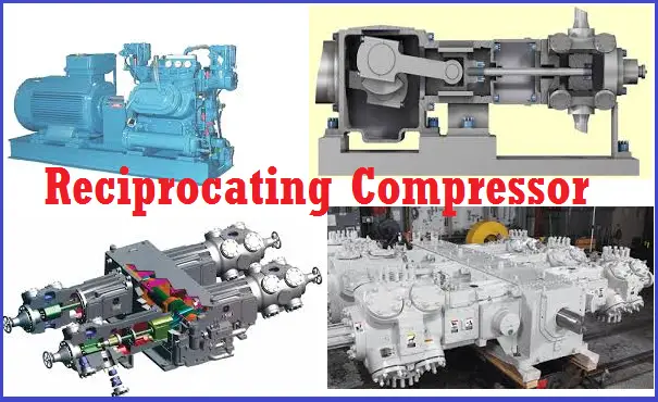
In a reciprocating compressor, a volume of gas is drawn into a cylinder; it is trapped and compressed by a crankshaft-driven piston and then the high-pressure gas is discharged into the discharge line. It is a positive displacement machine. At any production facility, reciprocating compressors are considered to be one of the most critical and expensive pieces of equipment and hence, require special attention. They are widely used in various industrial facilities to compress gases like:
- Air in compressed tool and instrument air systems
- Hydrocarbons in the refinery, chemical, and petrochemical plants
- Oxygen, Hydrogen, Nitrogen, etc. for chemical processing
- Various other gases for storage or transmission
Reciprocating compressors are widely used for compressing dry gases requiring a high compression ratio (discharge pressure/suction pressure).
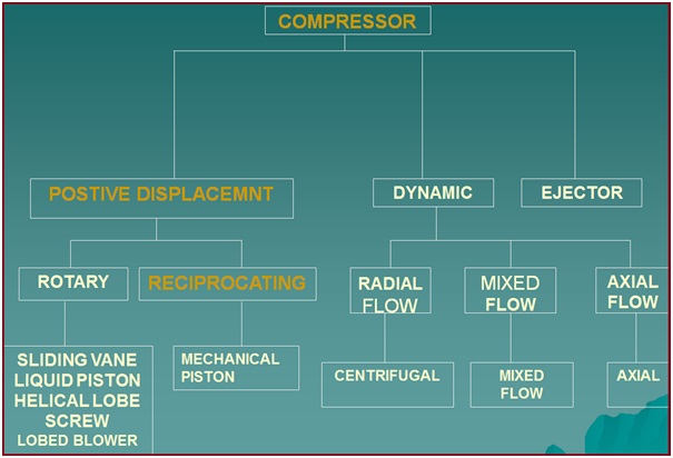
The gas to be compressed enters through the suction manifold and then it flows into the compression cylinder. A piston compresses the gas using a reciprocating motion via a crankshaft. Because of the reciprocating motion of the piston, such compressors are known as reciprocating compressors. The cylinder valves of a reciprocating compressor control the flow of gas through the cylinder; these valves act as check valves. Fig. 1 shows the classification of Compressors.
Types of Reciprocating Compressors
Depending on the discharge strokes per revolution of the crankshaft, there are two types of reciprocating compressors.
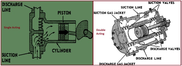
- Single – Acting compressor: It is a reciprocating compressor that has one discharge per revolution of the crankshaft. Gas is compressed by only one end of the piston. Contains only one spring-loaded inlet and outlet valve.
- Double–Acting Compressor: It is a reciprocating compressor that completes two discharge strokes per revolution of the crankshaft. Gas is compressed by both ends of the piston. Contains inlet and outlet valves at both ends. Most heavy-duty compressors are double-acting.
Fig. 2 Shows the typical configuration of a Single and double-acting reciprocating compressor.
Depending on the drive mechanism of the reciprocating compressor, they are of two types.
- Separable Reciprocating Compressor, and
- Integral Reciprocating Compressor
The following Table lists down major features of both reciprocating compressor types.
| Separable Compressor | Integral Compressor |
| The compressor and the driver can be separated as driven by separate drives like an electric motor or engine. | Integrally mounted power cylinders drive the compressor and hence can not be separated. |
| High-Speed Reciprocating Compressors. The typical Operating Speed is 900 -1800 rpm. | Low-Speed reciprocating compressors. The typical operating Speed is 200-600 rpm. |
| They are normally skid-mounted and the complete skid can be erected at the shop and transported. | Field Erected. |
| Lower Foundation loads. | Require heavy foundation. |
| Less vibration severity. | High vibration Severity. |
| Lower initial Installation Cost. | High Initial Installation cost. |
| High Maintenance Cost. | Low Maintenance Cost. |
| Low Efficiency. | High Efficiency. |
Depending on the number of compression stages before discharge, two types of reciprocating compressors are found:
- Single-Stage Reciprocating Compressor, and
- Multi-Stage Reciprocating Compressor
The main differences between single-stage and multi-stage reciprocating compressors are listed below
| Single-Stage Reciprocating Compressor | Multi-Stage Reciprocating Compressor |
| Contain Single Cylinder | Contains multiple cylinders |
| Gas is compressed only once | Gas is compressed multiple times before the final discharge |
| Lower Compression ratio | Higher Compression ratio |
| Less Efficiency and Reliability | Improved Efficiency and better reliability |
| Lower Cost | Higher Cost |
| Intermittent Operation | Continuous Operation |
Depending on the speed, Reciprocating compressors are classified as either high speed or slow speed. Typically, high-speed compressors run at a speed of 900 to 1200 rpm, and slow-speed units at speeds of 200 to 600 rpm.
Working of a Reciprocating Compressor
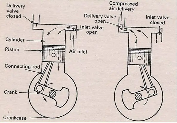
As the name signifies, a reciprocating compressor works by the to and fro motion of the piston inside a cylinder.
When the piston moves downward, it creates a vacuum between the piston top and the cylinder head. This causes the inlet valve to open and low-pressure gas fills in. During this time, inlet valves remain open and discharge valves remain closed.
Next, the piston moves upward forcing the inlet valve to close and the gas is trapped in the cylinder. As the piston moves further the area between the piston head and cylinder reduces which results in gas compression. When the gas pressure exceeds the discharge valve spring resistance, it opens and the gas is transferred to the receiver. The same process is repeated.
Advantages of a Reciprocating Compressor
The main advantages of a reciprocating compressor are:
- Broadest pressure range in the compressor family (vacuum to 3000 bar).
- Multiple Services on one compressor frame. On a multi-stage frame, each cylinder can be used for separate gas services. For Example, One cylinder is dedicated to propane refrigeration with balance cylinders dedicated to product gas.
- Lower capital cost.
- Can handle wide variations in capacity with much more ease than any other type.
- Complete skid-mounted units allow easy transportation and installation and relocation.
- In general, higher efficiencies compared to centrifugal type for the same operating conditions.
- Especially suited for low molecular weight applications.
Application limits of Reciprocating Compressors
Reciprocating compressors are limited by the following parameters in their applications:
- Flow: they can handle very low flows without significant loss in efficiency.
- Capacity: High capacity is limited by cylinder size, stroke length, and speed.
- Pressure: Very high pressures up to 3000 bara are practically applied.
- Discharge Temperature: Discharge temperature is generally restricted to 135⁰C. For hydrogen-rich services (molecular weight less than or equal to 12) and non-lubricated cylinders, the discharge temperature shall not exceed 120⁰C. Compressed air applications allow higher discharge temperatures
- Compression ratio: Typical compression ratios for a single-stage reciprocating compressor are 1.2 to 4.0. The Compression Ratio (Pd/ Ps) is limited by the following;
- Maximum Discharge Temperature
- Allowable Rod Load
- Cylinder Volumetric Efficiency
- Horsepower: In gas processing applications power ratings of more than 7.5 MW are rarely found. Special machines with power ratings as high as 30 MW are available for other applications.
- Rotating Speed: Low to moderate speeds typically at 300-700 rpm with motors. Moderate to high speeds typically at 600-1800 rpm with motors or gas engines (field gas compression, gas plant, pipeline). Low to moderate speeds in accordance with API STD 618. Moderate to high speeds in accordance with ISO STD 13631.
Codes and Standards for Reciprocating Compressor
Various codes and standards govern the design and manufacture of reciprocating compressors like:
- API Standards: API-11P (Packaged Reciprocating Compressors) and API-618 (Reciprocating Compressors for Petroleum, Chemical, and Gas Industry Services)
- ISO Standards: ISO-13707 and ISO-13631
- Shell DEP: DEP 31.29.40.31
- API RP 688 for Pulsation and Vibration Control.
Construction of Reciprocating Compressors
The construction of Reciprocating compressors can be divided into two main areas:
- Gas end.
- Power end.
Gas End Parts of a Reciprocating Compressor
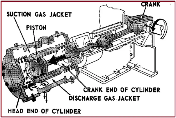
The main gas end Parts of the reciprocating compressor (Fig. 4) are
- Cylinder
- Head
- Piston & piston rod.
- Suction valves.
- Discharge valves.
- Piston rod Packing
- Suction and discharge gas jacket
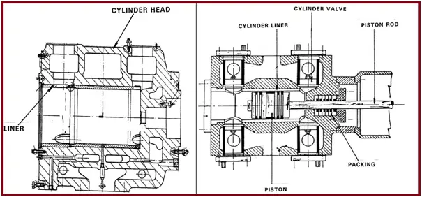
Cylinder & Liner
The piston reciprocates inside a cylinder of the reciprocating compressor. To provide for reduced reconditioning cost, the cylinder may be fitted with a liner or sleeve. A cylinder or liner usually wears at the points where the piston rings rub against it. Because of the weight of the piston, wear is usually greater at the bottom of a horizontal cylinder.
Head
The ends of the cylinder are equipped with removable heads, these heads may contain water/liquid jackets for cooling. One end is called the head-end head and the other crank-end head. The crank-end contains packing (a set of metallic packing rings) to prevent gas leakage around the piston rod.
Piston
- The piston moves forward and backward to suck and compress the gas. It pushes the gas in the discharge pipe during the compression stroke.
- For low-speed (up to 330 rpm) and medium-speed reciprocating compressors (330-600 rpm), pistons are usually made of cast iron.
- Up to 7” diameter cast iron pistons are made of solid bars. Those of more than 7” diameters are usually hollow (to reduce cost).
- Carbon pistons are sometimes used for compressing oxygen and other gases that must be kept free of lubricant.
Clearance in Piston and Cylinder
As the reciprocating compressor reaches operating temperature, the piston and rod expand more than the liner/cylinder does. In order to prevent seizure adequate clearance should be provided. Similarly, end clearance is also important.
A cold piston is usually installed with one-third of its end clearance on the crank end and two-thirds of its end clearance on the head end.
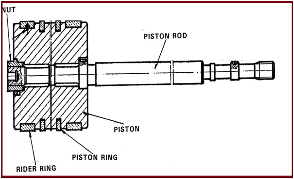
Piston Rings (Fig. 5)
Piston rings provide a seal that prevents or minimizes leakage through the piston and cylinder liner. Metal piston rings are made either in one piece, with a gap, or in several segments. Gaps in the rings allow them to move out or expand as the compressor reaches operating temperature. Rings of the heavy piston are sometimes given bronze, Babbitt, or Teflon expanders or riders. Lubrication is a must for metallic rings. Teflon rings with Teflon rider bands are sometimes used to support the piston when the gas does not permit the use of a lubricant.
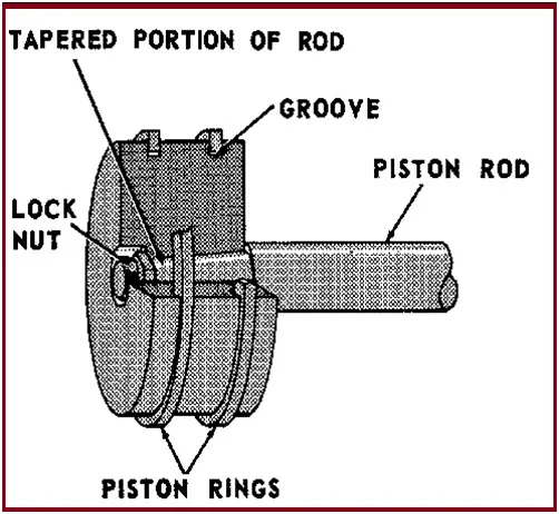
Piston Rod and Piston (Fig. 6)
The piston rod is fastened to the piston by means of a special nut that is prevented from unscrewing. The surface of the rod has a suitable degree of finish designed to minimize wear on the sealing areas as much as possible. The piston is provided with grooves for piston rings and rider rings.
Piston rod packing
Piston rod packing ensures the sealing of the compressed gas. The piston rod packing consists of a series of cups each containing several seal rings side by side. The rings are built of multiple sectors, held together by a spring installed in the groove running around the outside of the ring.
The entire set of cups is held in place by stud bolts. Inside channels are there for cooling, gas recovery, and lubrication of the piston rod packing.
Oil Seal
An arrangement of scraper rings serves to keep the oil, entrained by the piston rod, from leaking out of the crankcase. The oil scraped is returned to the crankcase reservoir.
Valves
Valves (Suction and Discharge valves): allow gas to enter into the piston during the suction stroke and allow gas to go out into the discharge line during the compression stroke.
There are normally three types of valves, which are
- Plate valve.
- Channel valve.
- Poppet valve.
Power End of a Reciprocating Compressor
Parts of reciprocating compressors that assist in transferring power and converting rotary motion into reciprocating motion are grouped in this category.
Crank Case
The crankcase (Fig. 7) supports the crankshaft. All bearing supports are bored under setup conditions to ensure perfect alignment. The crankcase is provided with easily removable covers on the top for inspection and maintenance. The bottom of the crankcase serves as the oil reservoir. The main pump for lubrication of the crank mechanism is placed on the shield mounted on the side opposite the coupling and is driven by the reciprocating compressor.
Crankshaft
Crankshaft receives the power from the Driver and transfers it to the piston. The crankshaft is built in a single piece. On the inside of the shaft are holes for the passage and distribution of lube oil.
Main Bearings
The main bearings are built in two halves, made of steel, with an inner coating of antifriction metal.
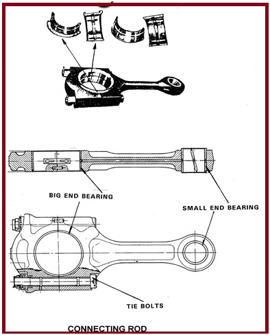
Connecting Rods
Connecting rod (Fig. 8) connect the crankshaft with the piston rod.
The connecting rod has two bearings. The big end bearing is built in two halves. It is made of metal with an inner coating of antifriction metal. The connecting rod’s small end bearing is built of steel, with an inner coating of antifriction metal. A hole runs through the connecting rod for its entire length, to allow passage of oil from the big end to the small end bush.
Crosshead
Crosshead fastens the piston rod to the connecting rod. The sliding surfaces of crossheads are coated with antifriction metal like Babbit shoe. That permits it to slide back and forth within the crosshead guides. The shoes have channels for the distribution of lube oil. The lubrication is obtained under pressure; it comes out from the two guides of the crosshead slide body.
The connection between connecting rod and crosshead is realized by means of a gudgeon pin. The piston rod is connected to the crosshead by a nut.
Distance piece
The distance piece is used to separate the Gas end and Power End of the Reciprocating compressor.
API 618 defines 4 types of distance pieces for a reciprocating compressor which can be used based on the criticality of service.
- Type A – Short single compartment (Where oil carryover to piston packing is acceptable)
- Type B – Long Single Compartment (Where oil carryover to piston packing is not acceptable)
- Type C – Long-long two-compartment (For critical services like Oxygen and Hydrogen)
- Type D – Long-short two-compartment (For Process gas services)
The distance piece is provided with a drain and vent arrangement and if required continuously purge with buffer gas.
Pulsation Dampeners /Bottles for Reciprocating Compressors
Pulsation bottles are provided at suction and discharge to the reciprocating compressor, to keep the pulsation within the desired limit.
A pulsation study was carried out to decide the minimum volume of pulsation bottles.
Lubrication of Reciprocating Compressors
Lubricants reduce friction and therefore wear between moving reciprocating compressor parts. The lubricant also serves as a coolant. Fig. 9 shows a typical Lubrication System.
Generally, two types of systems are used to lubricate the positive displacement compressors.
- SPLASH SYSTEM
- FORCED FEED LUBRICATION
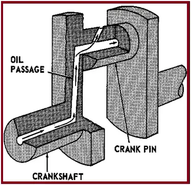
Splash System
It is used in older machines. The level is maintained in the crankcase. Oil is splashed up by the rotation of the crank and the counterweight into the collecting ring. Centrifugal force throws the oil outward through an oil passage to the crank pin.
Forced FEED Lubrication
A pump is used to feed the oil. Oil is pumped under pressure to the required parts. The following are the main parts of the system
Reciprocating Compressor Capacity Control Method
- By Recirculation
- By VSD
- By Valve Un-loader
- By Volume clearance pocket
Reciprocating Compressor vs Rotary Compressor
The main differences between a reciprocating compressor and a rotary compressor are tabulated below:
| Reciprocating Compressor | Rotary Compressor |
| Uses a piston for reciprocating action | Uses rollers |
| More Efficient | Less efficient |
| Expensive and more maintenance requirement | Cheaper option with less maintenance |
| Complex design and construction | Simple design |
| Less Life Span | Longer Life Span |
| High Compression Ratio | Low Compression ratio |
| Low-Speed Compressor | High-Speed Compressor |
| Complicated Lubrication | Simple Lubrication |
| Balancing is a major problem | No balancing problem. |
| High vibration tendency | Low Vibration tendency. |
Few more useful resources for you…
Articles related to Compressor
Articles Related to Pumps
Piping Design and Layout Basics
Piping Stress Analysis Basics
Piping Materials Basics
Articles Related to Mechanical Design
Articles Related to Process Design
Articles Related to Heat Exchanger
Thankyou sir for wanderfull article with details.
If possible please also include maintenance requirement/procedure whcich would be very helpful for us as piping layout engineers
Thanks
According to Value Market Research, the latest technology trends and global market opportunity analysis in the Reciprocating Compressor Market industry growing with a high CAGR in the upcoming year.
Thank you for the valuable information. Would please advise on the difference between Non-lub and lube compressors types and pros and cons?
hi anup, basically where is the fix point of reciprocating compressor installed at skid?