
A water hammer is a hydraulic shock that occurs in a piping system when a fluid (usually water) is suddenly stopped or forced to change direction. This sudden change in the fluid’s momentum can create a pressure surge that travels through the piping system, causing a loud banging noise, and vibrations, and potentially damaging the system.
Water hammer occurs when a valve is closed too quickly, causing the fluid to stop abruptly, or when the flow direction of the fluid is suddenly changed. The pressure surge created by the water hammer can be many times greater than the normal operating pressure of the system, potentially causing pipes to burst or fittings to fail.
Water hammer can be prevented or minimized by designing the piping system with gradual changes in direction and using properly sized piping and fittings. Additionally, valves should be closed slowly to prevent sudden changes in the flow direction, and air vents or expansion tanks can be installed to absorb pressure surges.
Water hammer can also be controlled by using pressure relief valves or surge tanks to release excess pressure before it can cause damage to the system. It’s important to address the water hammer promptly to prevent damage to the piping system and ensure safe and efficient operation.
It is well-known that water hammer is caused in a piping system by sudden closure or opening of the valves or due to pump trips. During those events, the pressure increases to a huge extent and that causes an unbalanced load in the piping system which is known as the Water hammer load. All these loads are created due to water hammer acts in the changes in directions and can be of sufficient magnitude to cause the piping system failure. So, during the design phase, water hammer analysis must be performed to calculate the water hammer loads and design piping and support systems to avoid failures. In this article, we will discuss the pipe stress analysis methodology for water hammer loads.
In piping systems, sudden changes in flow cause pressure unbalanced forces between elbows, valves, tees, reducers, and other inline components. These forces damage the piping system when it is not properly designed to accommodate them.
The main advantage of using PASS/START-PROF + PASS/HYDRO SYSTEM is that the 3D piping model can be easily converted between these software packages both ways.
3D piping model from PASS/START-PROF can be converted into the 3D piping model in PASS/HYDRO SYSTEM, then generate 3D water hammer loads for all nodes at certain moments of time (not only just in one node!) and pass it directly into stress analysis software PASS/START-PROF automatically (not manually!).
PASS Suite START-PROF + HYDRO SYSTEM allows us to model it very easily, just in several clicks, and help to find a way to reduce water hammer damage to the piping system. Let’s study how to perform stress analysis of the piping system from water hammer loads.
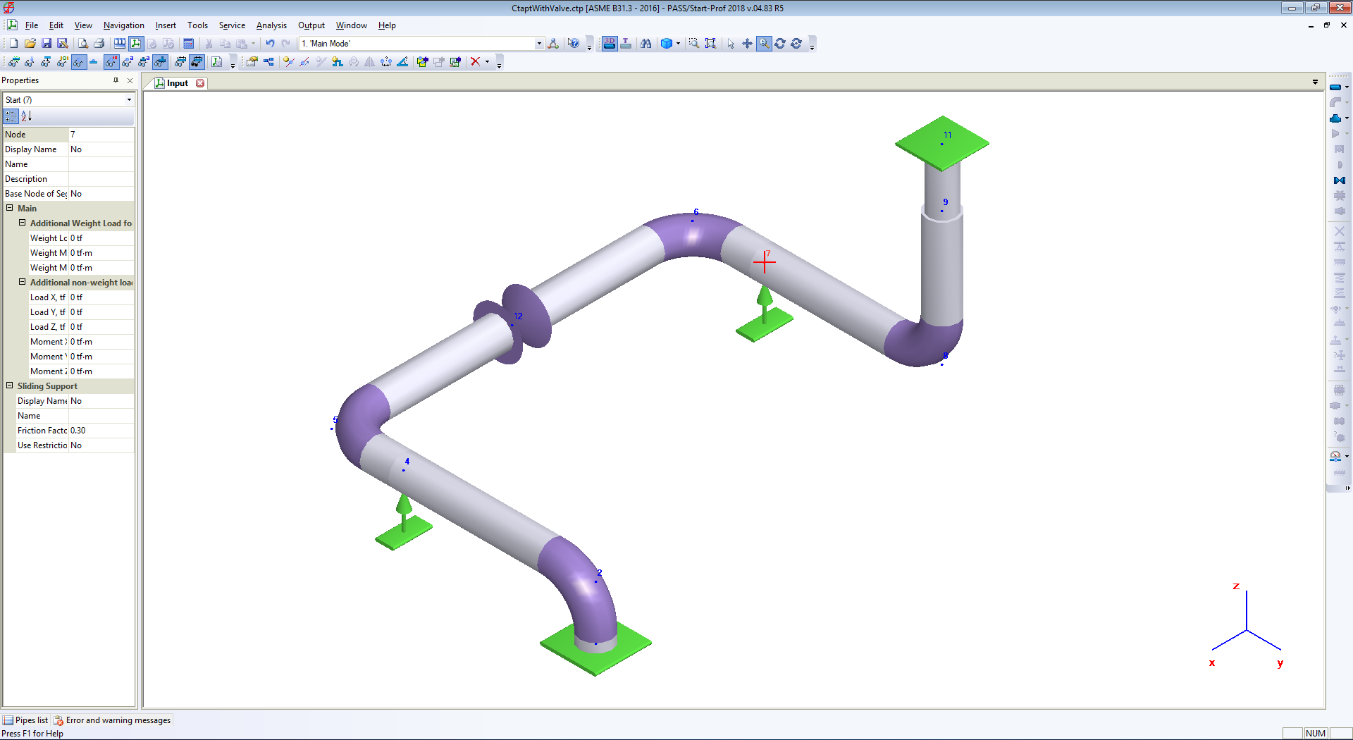
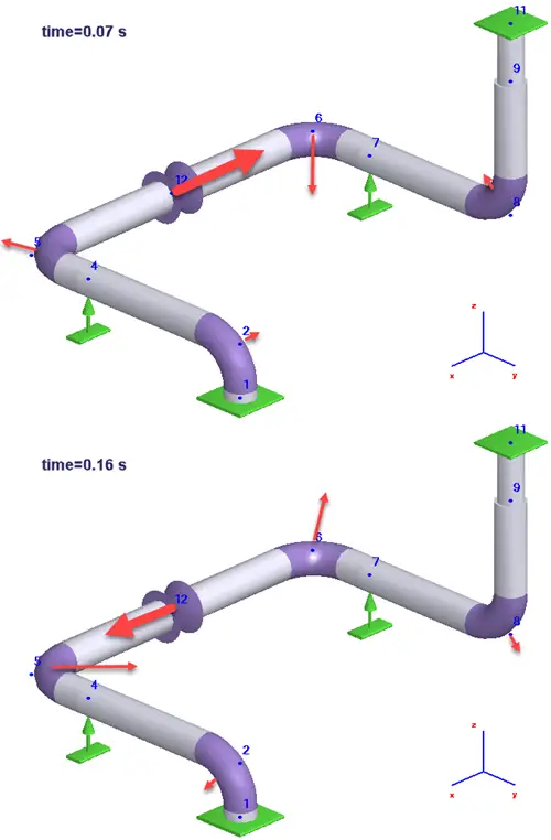
The simple piping system created in PASS/START-PROF software is shown below screenshot:
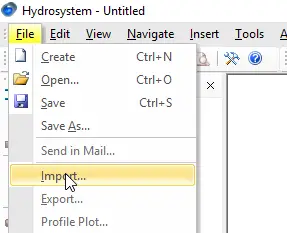
After saving the PASS/START-PROF file, we can open it using the PASS/HYDRO SYSTEM software.
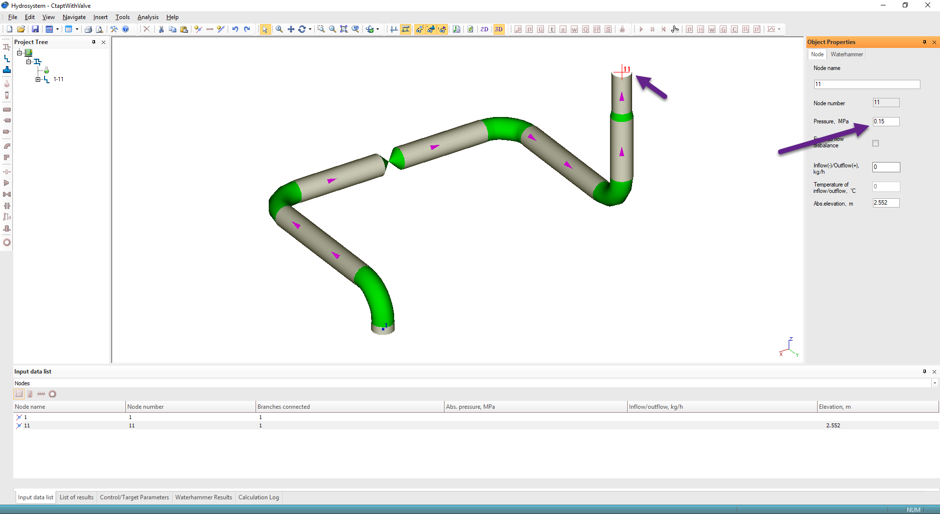
Set pressure 0.15 MPa at node 1, and 0.16 MPa at node 11
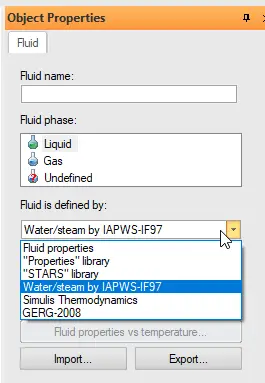
Choose water steam library
Define the period of surge analysis 2.5 sec, data output stem 0.01 sec, and dynamic load factor DLF=2.0.
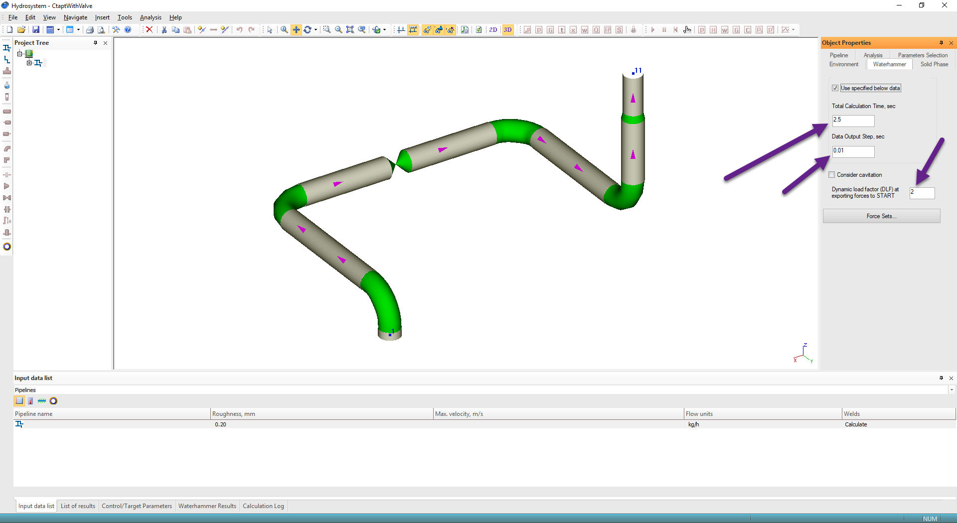
Select Valve in node 12 and in the “Waterhammer” tab set that valve is immediately closed.

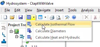
Run Isothermal Flow analysis
Run water hammer analysis
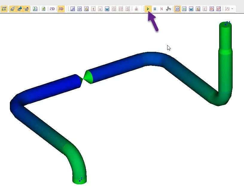
Running the Water Hammer Analysis
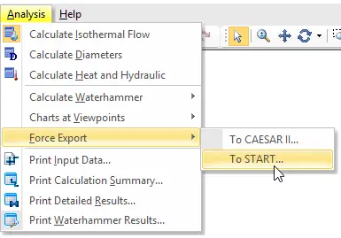
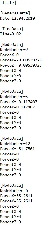
After that export unbalanced pressure forces into (.ctpf) file. Also, HYSROSYSTEM allows exporting data into (.frc) file that can be opened by CAESAR II.
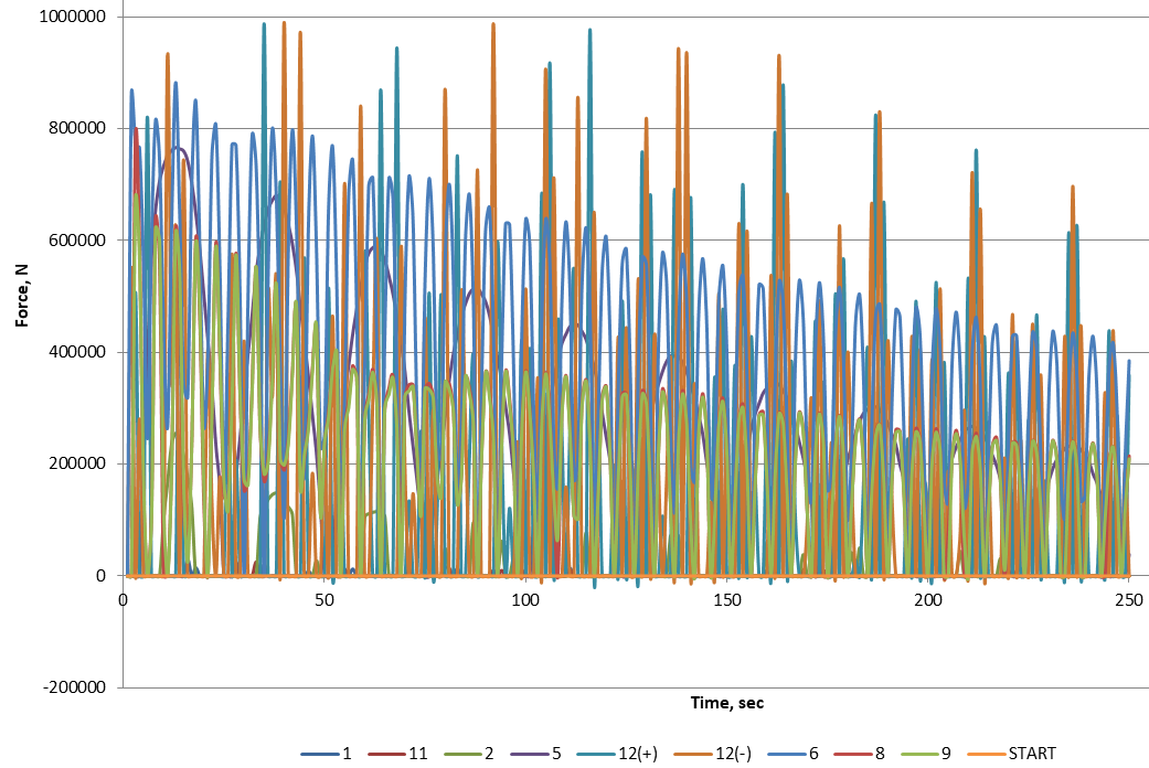
(.ctpf) file contains forces multiplied by DLF factor for all nodes in piping models at several most dangerous moments of time. The most dangerous moments of time is found automatically by HYROSYSTEM software.
This is the (.ctpf) file structure
This means, that PASS/HYDROSYSTEM generates unbalanced pressure loads for all nodes in the piping system at a certain moment of time.
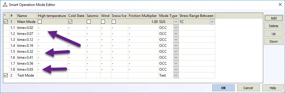
Now open PASS/START-PROF, open Operation Mode Editor and import waterhammer forces into first operating mode.
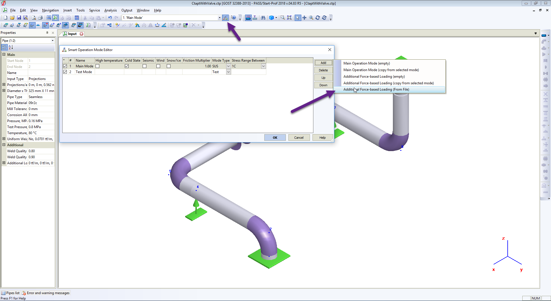
Eight additional force-based load cases are imported from the file
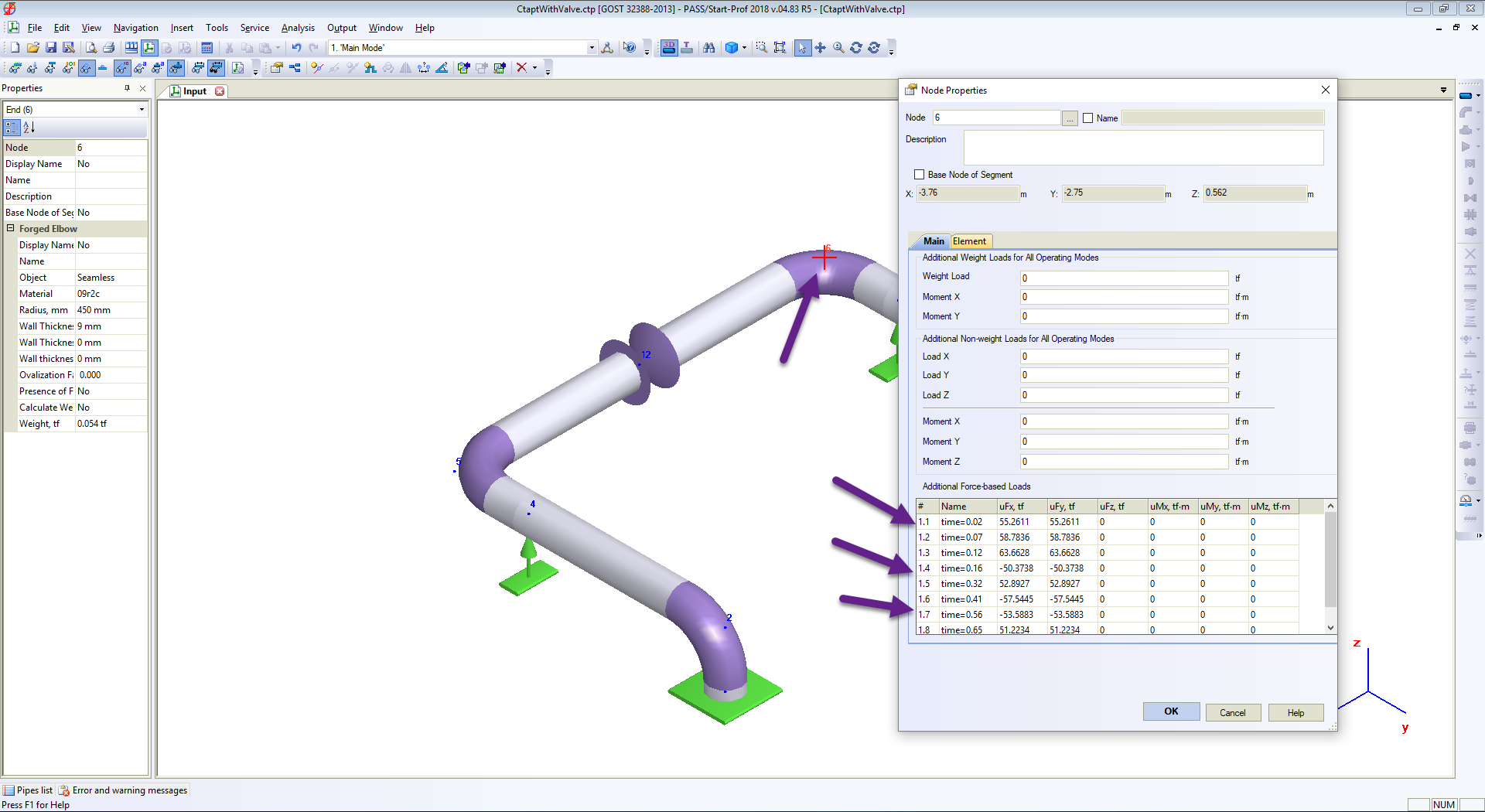
You can check the force values at any node properties
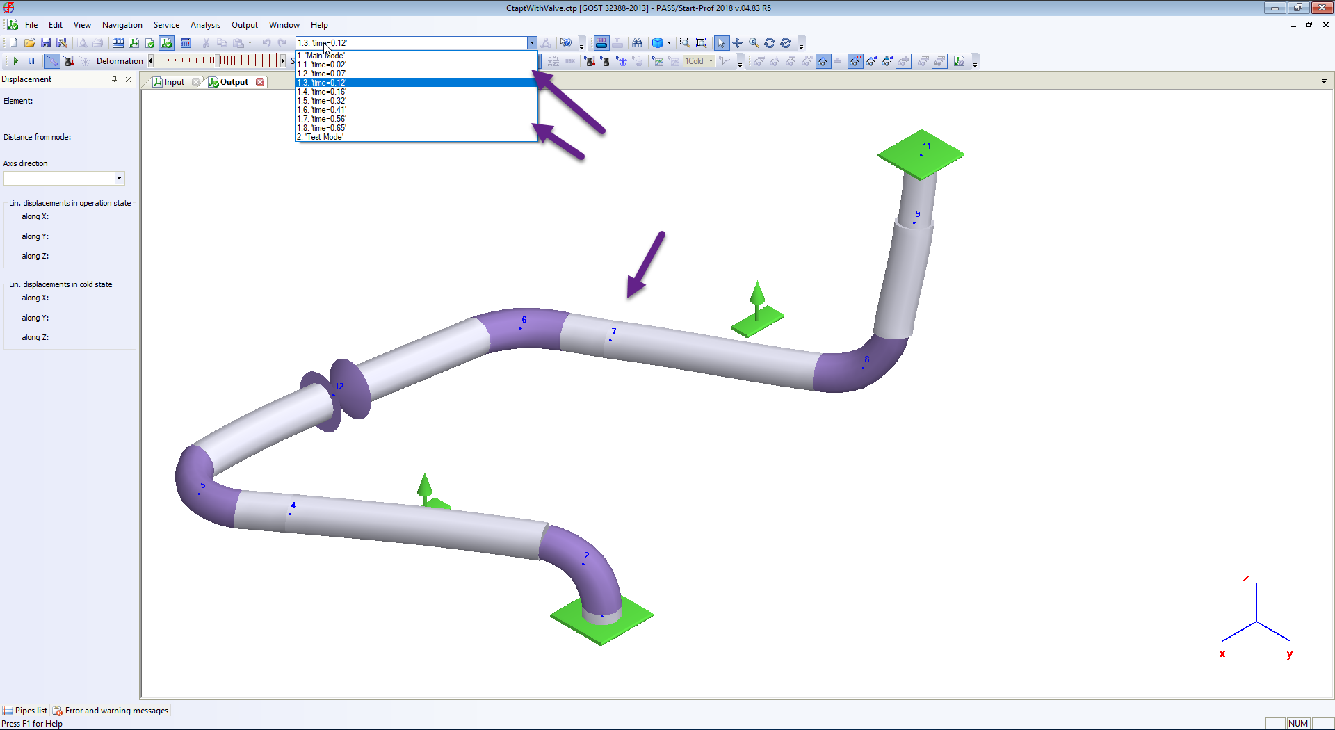
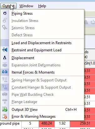
Now run piping stress analysis and see results
Deformed Shape at any moment of time
Stress table at any moment or time
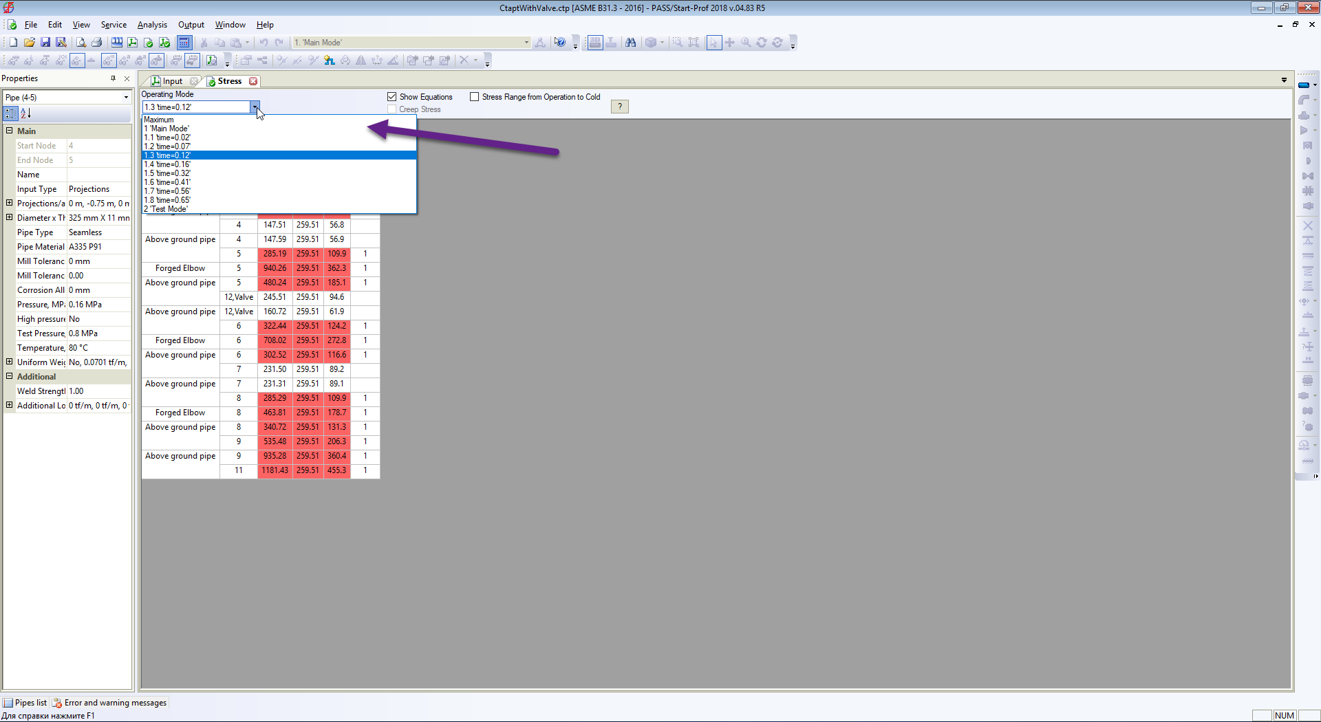
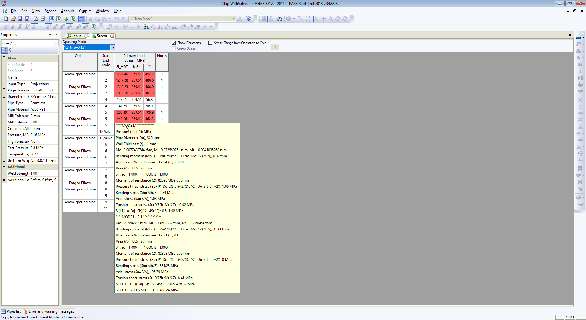
And maximum stresses from all load cases (static and all moments of time during waterhammer)
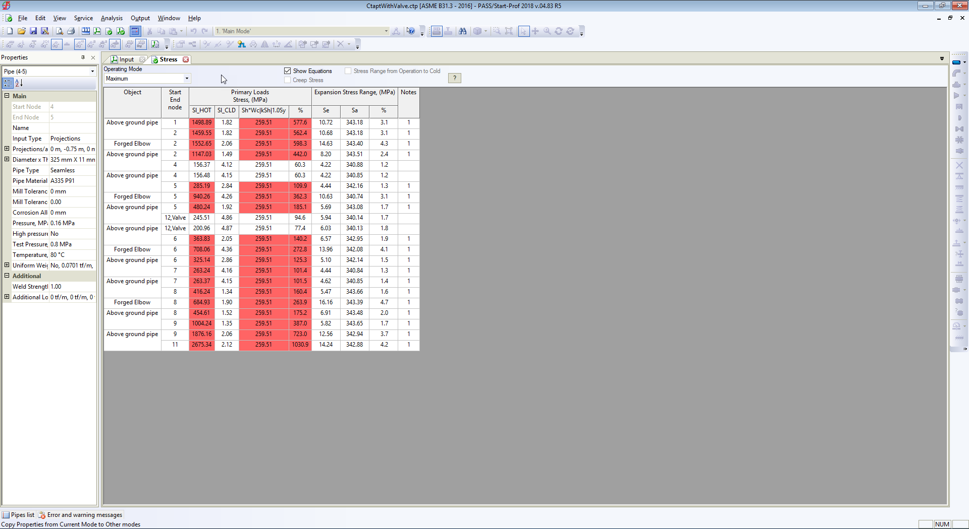
The same table can be checked for displacements, support loads, flange leakage, expansion joint deformations, etc.
Watch the following video with detailed analysis process described above:
Some more ready references for you…
Introduction to Pressure Surge Analysis
Water Hammer Basics in Pumps
Understanding Centrifugal Compressor Surge and Control
Stress Analysis using Start-Prof
what is the advantage of used spring loaded zero velocity valve in place of conventonal NRV in water supply pipe line pl discuss