
What is a Pile Foundation?
A pile foundation is a type of deep foundation that is used for supporting the structure and transferring the load at the desired depth by end bearing or skin friction. Pile Foundations (Fig. 1) are required when-
- The top layers of soil are highly compressible for it to support structural loads through shallow foundations.
- The rock level is shallow enough for end-bearing pile foundations to provide a more economical design.
- Lateral forces are relatively prominent.
- In presence of expansive and collapsible soils at the site.
- Offshore structures
- Strong uplift forces on shallow foundations due to the shallow water tables can be partly transmitted to Piles.
- For structures near flowing water (Bridge abutments, etc.) to avoid the problems due to erosion.
Types of Pile Foundation
Steel Piles
- Pipe piles
- Rolled steel H-section piles
- H section
Concrete Piles
- Pre-cast Piles
- Cast-in-situ Piles
- Bored-in-situ piles
Timber Piles: Composite Piles
Facts of Steel Piles
- Usual length: 15 m – 60 m
- Usual Load: 300 kN – 1200 kN
Advantages of Steel Piles
- Relatively less hassle during installation and easy to achieve the cutoff level.
- The high driving force may be used for fast installation
- Good to penetrate hard strata
- Load-carrying capacity is high
Disadvantages of Steel Piles
- Relatively expensive
- Noise pollution during installation
- Corrosion
- Bend in piles while driving
Facts of Concrete Piles
- Pre-cast Piles: Usual length: 10 m – 45 m; Usual Load: 7500 kN – 8500 kN
- Cast-in-situ Piles: Usual length: 5 m – 15 m; Usual Load: 200 kN – 500 kN
Advantages of Concrete Piles
- Relatively cheap
- It can be easily combined with a concrete superstructure
- Corrosion-resistant
- It can bear hard-driving
Disadvantages of Concrete Piles
- Difficult to transport
- Difficult to achieve the desired cutoff
Types of Piles Based on Their Function and Effect of Installation
Piles based on their function-
- End Bearing Piles
- Friction Piles
- Compaction Piles
- Anchor Piles
- Uplift Piles
Effect of Installation-
- Displacement Piles
- Non-displacement Piles
Displacement Piles
In loose cohesionless soils
- densifies the soil up to a distance of 3.5 times the pile diameter (3.5D) which increases the soil’s resistance to shearing
- The friction angle varies from the pile surface to the limit of compacted soil
In dense cohesionless soils
- The dilatancy effect decreases the friction angle within the zone of influence of the displacement pile (3.5D approx.)
- Displacement piles are not effective in dense sands due to the above reason.
In cohesive soils
- Soil is remolded near the displacement piles (2.0 D approx.) leading to a decreased value of shearing resistance.
- Pore pressure is generated during installation causing lower effective stress and consequently lower shearing resistance.
- Excess pore pressure dissipates over time and soil regains its strength.
- Example: Driven concrete piles, Timber or Steel piles
Non-displacement Piles
- Due to no displacement during installation, there is no heave in the ground
- Cast in-situ piles may be cased or uncased (by removing the casing as concreting progress). They may be provided with reinforcement if economical with their reduced diameter
- The enlarged bottom ends (three times the pile diameter) may be provided in cohesive soils leading to a much larger point-bearing capacity.
- The soil on the sides may soften due to contact with wet concrete or during the boring itself. This may lead to the loss of its shear strength.
- Concreting underwater may be challenging and may result in wasting or necking of concrete in squeezing ground.
- Example: Bored cast in-situ or pre-cast piles
Load Transfer Mechanism of Piles
With the increasing load on a pile initially the resistance is offered by side friction and when the side resistance is fully mobilized to the shear strength of soil, the rest of the load is supported by the pile end. At a certain load, the soil at the pile end fails, usually in punching shear, which is defined as the ultimate load capacity of the pile. Refer to Fig. 2 for the load transfer mechanism on a pile foundation.
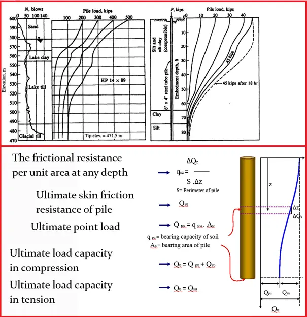
Bearing Capacity of Pile Foundation
The bearing capacity of the pile for both driven & bored is a combination of the friction part around the shaft of the pile through its length and the point bearing part at the tip of the pile
Qu (Ultimate Bearing Capacity of Pile)= Qp (Point Bearing) + Qs (Shaft Resistance)
For Driven Pile Bearing Capacity Calculation Two Methods are there
- Static method
- Dynamic method
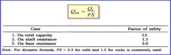
Allowable Pile Capacity
The factor of Safety shall be used by giving due consideration to the following points
- Reliability of soil parameters used for calculation
- Mode of transfer of load to the soil
- Importance of structure
- Allowable total and differential settlement tolerated by the structure
The equation in Fig. 3 shows the allowable capacity of a pile foundation.
Group Capacity of Pile
The bearing capacity of the pile group may be determined from
- Bearing capacity of the individual pile multiplied by the no of piles in the group
- All piles behave like a group of the pile where individual behavior is not predominant
The capacity shall be the minimum of the above cases.
If the pile is founded on rock or in progressively stiffer soil the pile group capacity shall be based on (1).
If the pile is deriving its support mainly from friction, the group may be visualized to transmit to the soil, as if from a column of soil enclosed by the piles. The ultimate capacity of the group may be computed following this concept, taking into account the frictional capacity along the perimeter of the column of soil as above and the end bearing of the said column using the accepted principle of soil mechanics.
Load Test on Pile Foundation
There are three types of test
- Vertical Compression
- Lateral load test
- Pull out test
Vertical Compression Load Test
Here compression load is applied at the pile top by hydraulic jack against rolled steel joist or suitable load frame and the settlement is recorded.
There are thereof vertical load test methods which are 1) Maintained load method, 2) Cyclic method, 3) CRP method
Lateral Load Test
The test may be carried out by introducing a hydraulic jack with a gauge between two piles or pile groups under test or the reaction may suitably be obtained otherwise. The jack provides the load against the lateral resistance between the piles. The displacement is measured at the cut-off level
Pull Out Test
Uplift force may be applied by means of a hydraulic jack with a gauge using a suitable pull-out setup. The pile should have adequate longitudinal reinforcement to take the pull-out load.
Design of Pile Foundation
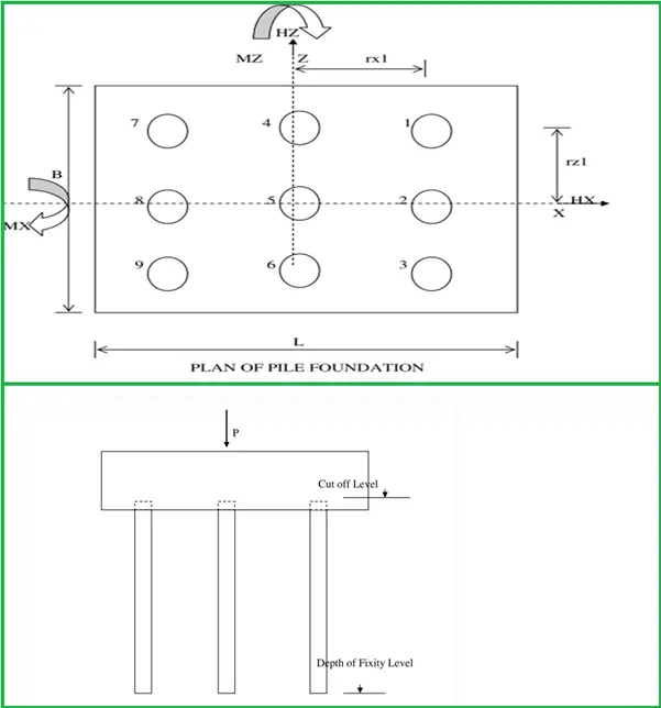
In Fig. 1 a Pile Foundation has been shown. The X-axis and Z-axis coincide with the CG of the pile group.
The pile foundation is subjected to Vertical Compression Load (P), Horizontal Load HX, HZ in X & Z direction respectively, and Moments MX & MZ in X & Z direction only.
So Maximum Vertical Load on Pile,
Load on Pile 1, V1= P/no of pile + Mx * r z1 / ∑rz2 + Mz * r x1 / ∑rx2
Find the maximum vertical Load on the extreme corner pile and check it with the pile capacity
where ∑rz2 = summation of rz2 of each pile
where ∑rx2 = summation of rx2 of each pile
Horizontal load on each Pile, H = √ (HX 2 + HZ2) / No of Pile
So deflection at pile head,
Δ = H (L1 + Lf)3 / 3EI for Free head pile
Δ = H (L1 + Lf)3 / 12EI for Fixed head pile
If the deflection is within 5 mm or H is less than The lateral pile capacity then it is ok otherwise increase the no of piles,
Now find the fixed end moment,
Mf = m H (L1 + lf) for Free Head Pile
Mf = m H (L1 + lf)/2 for Fixed Head Pile Where m is the reduction factor,
Now we have a vertical load on Pile, V1, and fixed end moment Mf. Design of the pile as a column has to be done on the basis of these forces keeping in mind that the minimum longitudinal reinforcement shall be 0.4 % and a maximum of 2%. The link shall not be spaced more than 250mm c/c.
Minimum reinforcement shall be provided for the pile length below the fixity level.
Few more useful resources for you..
Structural Platforms: An In-Depth Guide
A Short Presentation on Pile Foundation and its Design
An article on Tank Pad Foundation
An Introduction to Braced Connections
A short article on “Sun Shade for oil and gas industry and their Design”
Considerations for Project Site Selection
Thanks for the post.
Thanks for pointing out that steel piles have a high load carrying capacity. My husband and I are thinking about constructing a pool in our backyard and using steel piles as the foundation. I like that they are strong and last a long time, but are also not as expensive as other options.
Wow, I had no idea that piling could be used for structures where water is flowing near so that you can avoid erosion. For one of my classes at the university, we are learning about different foundations and I was assigned to research pile foundations. In my opinion, you should always talk to a professional if you are in need of a service or if you have any doubts or questions.