During the course of pipe stress analysis, we find a few lines in any complex project to have a very large diameter. Caesar II Support Modeling of such pipes always creates confusion on whether to consider radial thermal growth or to be modeled as centreline supporting. There is still confusion among several engineering organizations and the design approach varies. In this article, We will discuss pipe support modeling in Caesar-II, support selection, its detailing & functionality. In this article, Pipes /Pipelines having a diameter of more than 24’’ are considered large-diameter pipes.
Support Modeling Philosophy in Caesar II
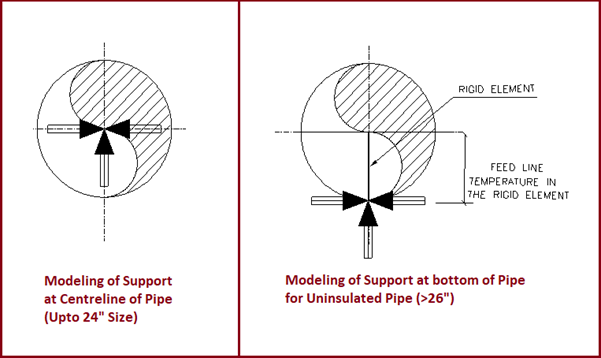
Up to 24’’ pipe size, support shall be modeled at the centerline of the pipe i.e. the radial expansion of the pipe shall be neglected & support shall be assumed to be acting at the center of the pipe as shown in Fig. 1
For the Large diameter bare pipes (>26″ NB), the Stress Engineer shall model a rigid element from the center of the pipe to the bottom of the pipe up to the supporting point considering the pipe radial expansion as shown in Fig. 1.
Fig. 1: Pipe Support Modeling for bare pipes at Caesar II
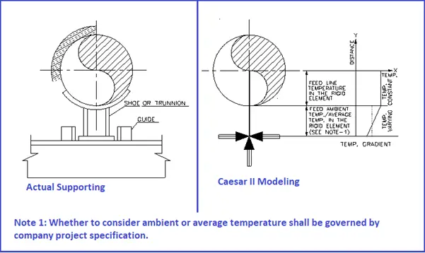
For Large diameter insulated pipes, the temperature gradient and the actual point of action of guide and resting can also be fed as shown in Fig. 2.
Fig. 2: Pipe Support modeling for large-diameter insulated pipes at Caesar II
The stress engineer shall decide whether to provide the reinforcing pad or not at the support point (trunnion type) in the following cases:-
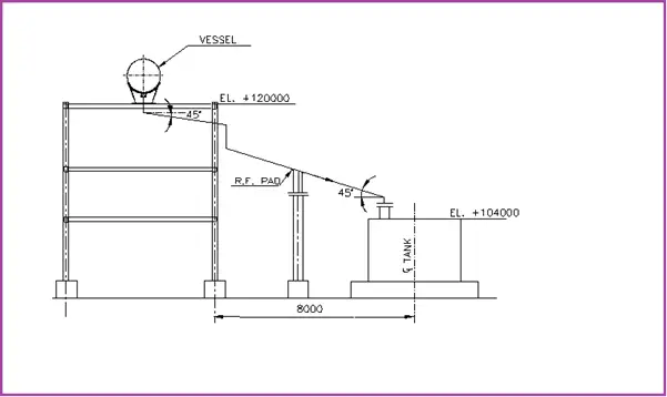
If the slope of the piping is more than 15˚, the Stress engineer shall decide whether to use a reinforcement pad or not, depending upon pipe size, support load, support function (Line Stop/Guide), unsupported pipe span, etc. Refer to Fig. 3 for an illustration.
Fig. 3: Use of R.F. Pad for Sloped Lines > 15˚
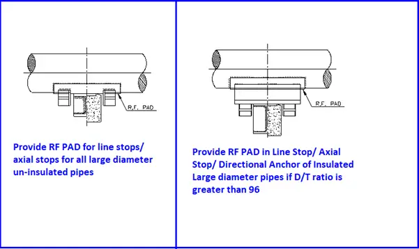
The reinforcement pad at the Directional Anchors or line stops for large pipes shall be used as shown in Fig. 4 below.
Fig. 4: Requirement of RF Pad for Supporting large diameter pipe
Irrespective of any size, the stress engineer shall provide a reinforcement pad for higher loads on the support based on the trunnion check calculation.
RF pad shall be provided at all support for thin pipes. The pipe shall be considered a thin-walled pipe if D/T> 96, where D is the outer diameter of the pipe and t is its thickness.
Wear Pad shall be used at all support locations in case of uninsulated large pipes
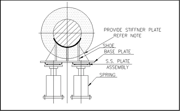
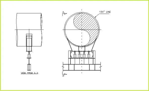
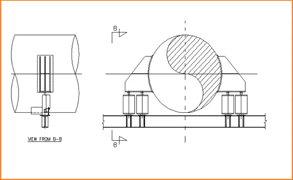
For large-diameter pipes, two or more bottom-type springs may be used as shown in Fig. 5, Fig. 6, and Fig. 7.
Fig. 5: Illustration of Two Bottom Springs used for Large pipes (Note: Provide stiffener plate if the shoe base plate extension is large)
Fig. 6: Illustrating Four Bottom Type Springs used at one Supporting Location with a guide for Large Pipes
Fig. 7: Illustration of Four Bottom Type Springs used for Large pipes
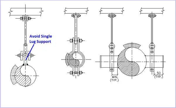
For large diameter pipes, it’s better to avoid single lug support due to the tendency of ovalization of the pipe because of Self-weight. Supporting shall be done using a pipe clamp or two trunnions having two different clamps instead of a single lug as shown in Fig.8.
Fig. 8: Use of clamps for supporting Large Pipes
Approach for Caesar Modeling Vs Actual Supporting
Generally, the following points are to be taken care of while converting Caesar II modeling into practical support. Depending upon supporting and practical function of the support we should revisit our Caesar II support modeling.
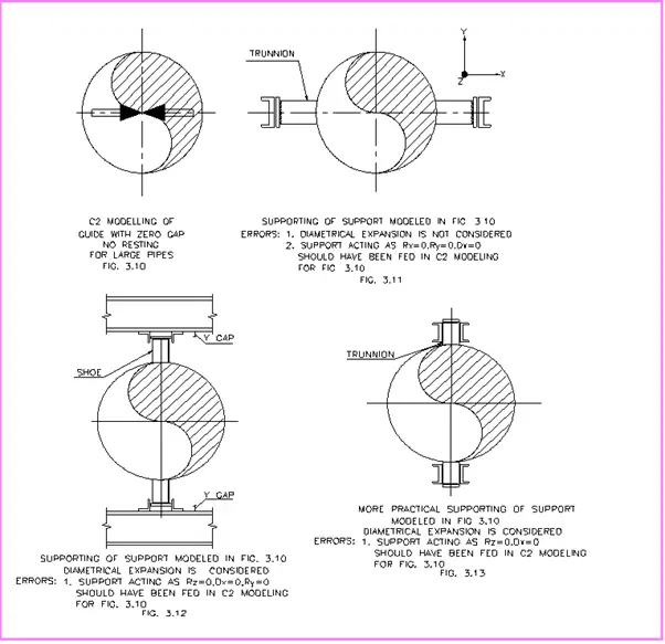
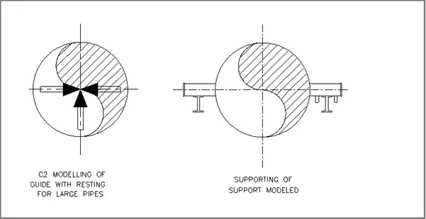
Supporting for guide modeled with zero gaps
Fig. 9: Guide modeling & supporting for Large Pipes
Supporting a guide with resting
Fig. 10: Modeling & supporting of Guide with resting for Large Pipes
These are a few standards practices. These may vary from one consultancy to another. Please provide your input in the comments section.
Few more articles related to piping supports for you..
I am a Mechanical Engineer turned into a Piping Engineer. Currently, I work in a reputed MNC as a Senior Piping Stress Engineer. I am very much passionate about blogging and always tried to do unique things. This website is my first venture into the world of blogging with the aim of connecting with other piping engineers around the world.
2 thoughts on “Guidelines for Modeling and Supporting of Large Diameter Pipes / Pipelines”
The remarkable corrosion resistance of Fe-Cr-Ni-Mo stainless steel in dilute acidic environments containing trace chlorides has been well-known over the years. The corrosion resistance arises because...
Subsea pipelines play a critical role in transporting oil and gas (hydrocarbon) from remote exploration and production sites to processing facilities and ultimately, consumers. They are essential...


How about long shoes be represented?
thanks
How can I model a support, in which a pipe with a larger diameter supports others with a smaller diameter?