Start-Prof can estimate the support loads and stresses caused by slug flow loads using the static method.


Additional dynamic loads caused by the slugs hitting the bends and tees must be considered. It can lead to the dropping of piping from the supports, exceeding the allowable nozzle and pump loads, etc.
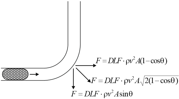
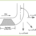
One of the methods for calculating the effect of slug flow loads is the static method. Vertical, horizontal, and resultant forces F can be determined by the formulas:
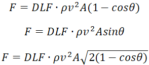
where
θ – bend angle (90 degrees, 45 degrees, etc.)
ρ – fluid density
v – slug velocity at the moment then it hits the bend
A – internal pipe cross-section area
DLF – dynamic load factor. For the static method recommended value is DLF=2
For straight tees load is calculated the same as for a 90-degree bend.
Calculated forces should be applied to the bends that the slug heats step by step.
Example
Example project file: SlugFlow.ctp . See how to open the piping model file
Input data:
- Diameter of discharge pipe: 0.219 m
- Wall thickness of discharge pipe: 0.016 m
- Product: steam + water
- Velocity 12.65 m/s
- Water density ρ=1000 kg/m³
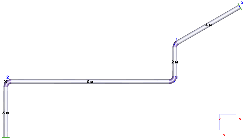
Calculation:
A=p∙(D-2t)²/4 = 3.14159∙(0.219-2∙0.016)²/4 = 0.027465 m²
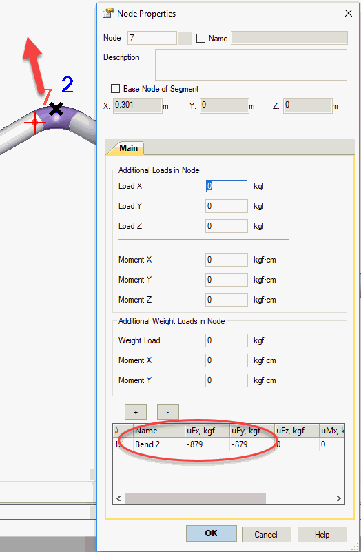
Loads on bend 2 will be:
F=DLF*ρ*v*v*A*(1-cos 90)=2*0.001*40*40*274.65*(1-cos 90)=8790 N=879 kgf
F=2*1000*12.65*12.65*0.027465*sin 90=8790 N=879 kgf
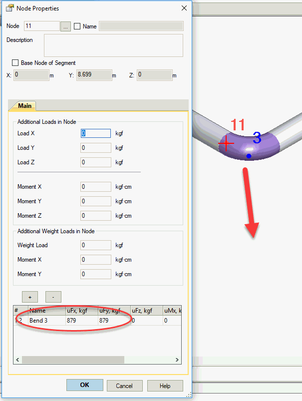
Loads on bend 3 will be:
F=DLF*ρ*v*v*A*(1-cos 90)=2*1000*12.65*12.65*0.027465*(1-cos 90)=8790 N=879 kgf
F=2*1000*12.65*12.65*0.027465*sin 90=8790 N=879 kgf
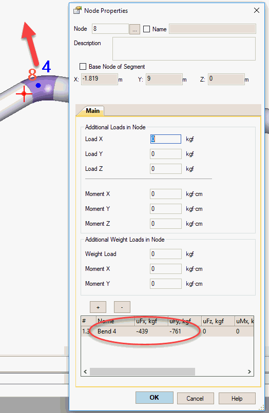
Loads on the bend 4:
F=DLF*ρ*v*v*A*(1-cos 60)=2*1000*12.65*12.65*0.027465*(1-0.5)=4390 N=439 kgf
F=2*1000*12.65*12.65*0.027465*sin 60=7610 N=761 kgf
The smaller the angle of the bend, the less the load on the bend, because the direction change angle of the slug is smaller.
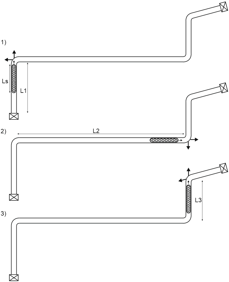
Using operation mode editor we should create one main operating mode (1) and three additional modes that will model slug loads on bends 2,3,4 (1.1, 1.2, 1.3). The mode type should be occasional.
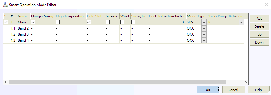
In the picture below three load modes are shown:
To apply loads we should add an additional node near bend 2 and apply calculated loads:
The same for bend 3:
And for bend 4:
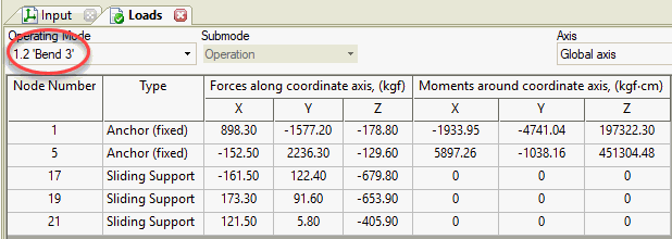
Piping stress caused by slug impact at the bend 3:
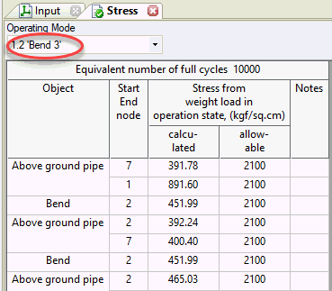
Support loads caused by slug impact at the bend 3:
In order to prevent the piping from falling from the supports, reduce the support loads, and reduce the stresses, you need:
- Add limit supports (limit stop supports with a gap, sway brace, and snubber), that will take the huge dynamic loads
- Try to change the piping layout to make pipe bend angles as small as possible
- Eliminate slug flow effect
Download this piping model file. See how to open the piping model file




Hi Alex,
You have not shown how to calculate forces on the flanges subject to slug flow, could you please show what are limits governing the resultant loads.