Is Low-Velocity Flow Bad?
Many of you are aware that high velocities in piping and pipelines lead to many operational and maintenance issues like piping vibration, noise, pipe material erosion, and a combined corrosion-erosion issue. American Petroleum Institute’s defunct document API RP 14E, defines a formula for determining erosional velocities in two-phase flows which states that actual flowing fluid velocities must be well below the calculated erosional velocities. International Standards Organization’s ISO 13703 points to the same philosophy regarding erosional velocities since it is based on API RP 14E, with the only difference being that the erosional velocity formula of API RP 14E is available in SI units.
The current discussion, however, deals with low velocities. The adjective used here is damaging for low velocities. As it is known that high velocities come with an adverse impact of vibrations or noise in piping systems, the undesirable impact of low velocities in piping is more subtle and long-term. The adjective damaging signifies this subtle and long-term effect of low velocities.
In this article, we will discuss the undesirable damaging effects that low velocities create in piping and pipelines. In the following paragraphs, the fluid flow in pipes and pipelines is categorized based on fluid type and the fluid phase.
The flow of Slurries inside Pipes
When fluid velocity is very low, solid particles separate from the fluid. Solid particles with a heavier density tend to settle down at the bottom of the pipe in a horizontal pipe run. This settling will be even more at elbows or bends where the flow is changing direction or where the pipe diameter is reducing. The damaging effect here is that over a period of time, a layer of solid builds up inside the pipe and pipe fittings thereby reducing the pipe diameter which leads to
- more pressure drop
- partial or full flow disruption
- the operating point of the pump moves towards shut-off leading to reduced pump efficiency and accelerated mechanical wear and tear of the pump and pump sealing system.
Flow of Liquids through pipelines
A typical example would be a hydrocarbon liquid with entrained water, where the hydrocarbon liquid is the continuous phase while the water is the discontinuous phase. At low flowing velocities, the entrained discontinuous phase water will drop out from the continuous phase hydrocarbon liquid to the bottom of the pipe. Water accumulation will occur in low points of the piping over the long term.
If the hydrocarbon liquid has even trace amounts of dissolved carbon dioxide or hydrogen sulfide, pipe/pipeline corrosion can occur. The mechanism of corrosion in simplistic terms is that carbon dioxide and/or hydrogen sulfide will react with the accumulated water in the pipeline leading to acid corrosion by the formation of Carbonic Acid (H2CO3) and/or Sulfuric Acid (H2SO4). Such corrosion can lead to the failure of carbon steel piping/pipeline over the long term.
Single Phase Gas Flow (with entrained liquids)
An example of such a system would be natural gas with entrained liquid water droplets and heavier hydrocarbons. When the flowing velocity is low, the flow may be stratified in the horizontal run of the pipe. The gas travels at the top part of the pipe and the liquid travels at the bottom part of the pipe, clearly parting the fluid into two parts. Liquid accumulation will occur at low points and direction changes in the pipe over a long period of time. The same problem of corrosion can occur as discussed for the flow of liquids. Additionally, the gas transport could see high-pressure drops and a reduction in flow, putting excessive loads on gas compressors.
Liquid accumulation over the long term in pipelines due to low velocities can also lead to intermittent slug flow in pipelines. The high momentum of liquid slugs can lead to structural damage to piping/pipelines and their supports.
Often natural gas pipelines have been found to have black powdery material (solids) in small amounts. The black powder could be because of corrosion products, trace amounts of solids carried over from gas treatment plants, mill scale, etc. Low flowing velocities in gas transmission pipelines can lead to accumulation and deposition on pipeline walls of the black powder over the long term and lead to excessive pressure drop and reduced flow.
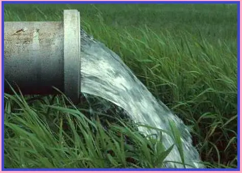
Flow velocities need to be kept above a threshold velocity also known as minimum entrainment velocity to prevent black powder deposits.
3-phase flow (Gas-Liquid-Liquid with Oil as continuous phase)
A typical example of such flow will be crude oil from reservoirs with associated dissolved gas and free water. At Low flowing velocities, similar problems related to corrosion will arise. Additionally, if the crude oil is heavy containing asphaltenes, then reduced flow velocities for a given pipeline will drastically increase the asphaltene deposition rate on the pipe walls. So there could be partial or total flow stoppage in the long run. This will require costly cleaning operations for the full restoration of pipeline operations.
Quantification of Minimum Velocities
Quantification of minimum velocities in piping or pipeline systems is important. For unlined carbon steel pipelines that transport light crude oil or condensate or any other liquid hydrocarbons containing entrained water even in a very small quantity (e.g. 1% water cut), the velocities should not be allowed to fall below 1.5 m/s to prevent water drops out.
For gas pipelines, however, the normal range of fluid velocities should be 5 to 10 m/s. For bone-dry gas, velocities up to 20.0 m/s may be allowed. However, for higher velocities, design considerations for noise and flow-induced vibration prevention have to be incorporated during all operational scenarios.
As mentioned earlier, black powder in natural gas pipelines will not be entrained at low gas velocities. This may lead to accumulation at some portion of the gas pipeline over a long duration. The entrainment velocity for these very fine particles is a function of their micron size. Generally, for a particle size of 1 micron to remain entrained, the gas velocity should be in the range of 2.5 to 4.5 m/s, depending on the pipe size.
Measures to prevent low velocities
In intermittent or batch transfer operations, when demand is low at the receiving station, continue pumping at the same high rate as required for peak demand but for a shorter duration. There is no need to reduce the flow rate for low demand in batch transfer operations. Standard Operating Procedures (SOPs) should address such turndown or low-demand scenarios without reducing the flow and thus the velocity.
Measures to mitigate low velocities
In prolonged turndown scenarios and continuous operations, low flow velocities are inescapable. To get rid of such problems associated with less fluid velocities, the following measures could be implemented:
- Addition of compatible anti-corrosion and anti-scale additives in the piping/pipeline system.
- Injection of compatible emulsifying agents in liquid hydrocarbon-water systems to prevent phase separation occurring at low velocities.
To summarize, low flowing velocities in pipes and pipelines can create issues like scaling and deposit formation, corrosion, etc. However, appropriate operational measures can be used to prevent operations at low velocities.
Please click here if you are interested in more Process Design related Articles




Greetings,
This is so informative. Kindly write about vibration in piping systems and ways to prevent it while designing a system.
Thanks and Regards,
Aswin Ajith