
Control Valve Sizing is a procedure of deciding the appropriate type and size of the control valve to optimally satisfy the requirements of fluid flow management. This article will describe the Control Valve Sizing Procedure with some details of related headings like Valve Flow Terminologies, Control Valve Characteristics, Cavitation, Flashing, etc.
Control Valve Flow Terminologies
The following control valve terminologies are required to define before we proceed with the control valve sizing steps.
- Pressure Drop: It is the difference between the upstream pressure and downstream pressure of the control valve.
- Cv (Flow Coefficient): The Cv is the number of U.S. gallons of water flowing during one min. at 60 Deg F through a restriction and the pressure drop through this restriction is 1 psi.
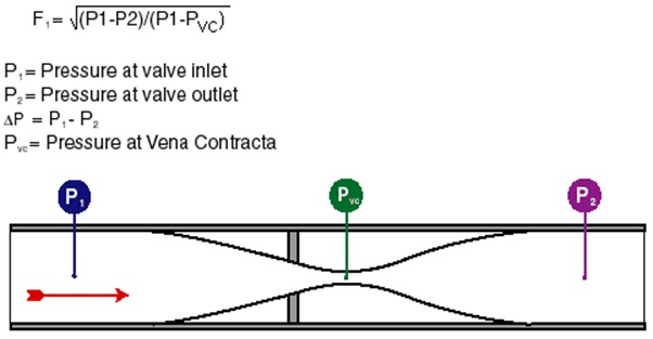
- Vena contracta: The vena contracta is where the jet of flowing fluid is smallest.
- Choked or critical flow: The flow is said to be choked when:
- Vena contracta is filled with vapor from cavitation or flashing.
- Fluid velocity at vena contracta reaches sonic.
- Vapor pressure: It is the pressure at which the given liquid will vaporize at the given temperature
- Cf (Critical Flow Factor): The Cf factor is an indication of the valve’s vena contracta pressure relative to the valve’s outlet pressure.
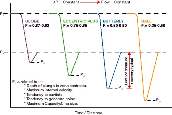
Pressure Recovery Factor in Control Valve Sizing
Control Valve Characteristics for sizing a control valve
Valve characteristics describe the relationship between valve travel and flow rate. Control Valve Characteristics are determined by the Design of the Valve Trim.
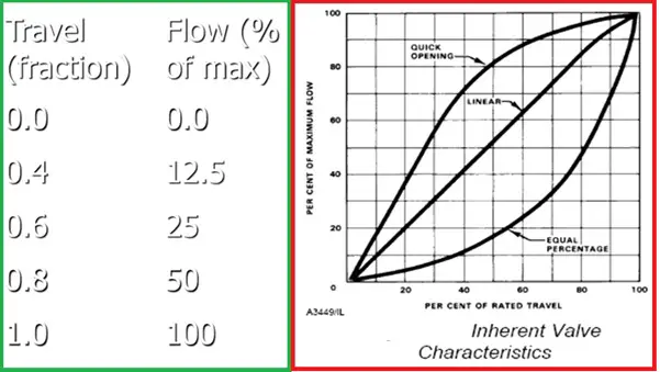
Inherent Characteristics
Expresses the relationship between the valve travel and flow rate for a constant pressure drop across the control valve.
- Quick Opening-On-off control with no throttling.
- Linear-Flowrate is linear with plug position.
- Equal Percentage-Equal increment of travel produces an equal % change in the flow.
Relationship between % Flow & % Valve Opening
A typical Characteristic of an Equal percentage Valve
Installed Characteristics
- Installed Characteristics are what really matter to a process engineer.
- Expresses the relationship between the valve travel and flow rate for a varying pressure drop across the control valve.
- Installed characteristics of the Equal percentage valve are nearly linear when pressure drop varies with the flow.
Installed vs Inherent characteristics:
The inherent flow characteristics do not reflect the actual performance of the valve as installed. The ideal condition of constant valve pressure drop (∆P) is unlikely to be true and the ‘operating’ characteristics will have a deviation from the inherent characteristics.
The deviation in the characteristics depends on the pressure drop variation across the control valve, as the control valve operates from minimum flow at its initial travel position to its maximum flow at its fully opened position.
Selection of Valve Characteristics for Control Valve Sizing
The following method should be used for control valve sizing
- Choose Equal percentage characteristics, if Pvalve < 70% of system Pressure Drop
- Choose Linear characteristics, if Pvalve > 70% of system Pressure Drop
Data Required for Control Valve Sizing
A combination of theory and empirical data should be used for control valve sizing and selection. Typically, the following data are used for control valve sizing:
- Operating Flowrates:– Maximum flow; Normal flow; Minimum flow
- Fluid Properties:-Fluid Phase; Molecular Weight; Vapor Pressure; Ratio of specific heats; Compressibility; Specific gravity; Viscosity
- Parameters:- Source Pressure; Destination pressure; Design pressure; Operating temperature; Shut off Pressure
Important Parameters for Control Valve Sizing and Selection:
- Valve size or valve coefficient (Cv)
- Pressure-Temperature rating
- Flow medium
- Service requirements (flow regulation or on-off type)
- Material of construction
- Valve Action (Normally Open vs. Normally Closed)
- Precision control
- Leakage or Tight shut-off
Control Valve Sizing Procedure
Rangeability:
Rangeability is the ratio of maximum to minimum controllable Cv. It is common practice to select a control valve within the following range:
Maximum flow:
- Valve opening <= 95 % for Equal Percentage Trim
- Valve opening <= 90 % for Linear and Quick Opening Trim
Normal flow: Valve opening should be at least 60 %
Minimum flow: Valve opening >= 10 %
Control valves do, what they are told!
The need for the fail-safe position
- Fail to Open (FO)
- Fail to Close (FC)
- Fail Last
FC / FO schematic
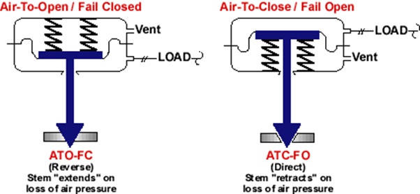
Double Acting Actuator
Control Valve Sizing Calculation
Sizing control valve for Maximum flow-
- Estimate Maximum required flow
- Calculate the system pressure drop without the valve
- Choose a valve that will pass maximum flow when about 90% open.
Size for minimum flow-
- Follow the same procedure as above and choose a valve that will pass minimum flow when about 10% open
Control Valve Sizing for Normal flow-
- Follow the same procedure and choose a valve that will pass normal flow when about 60-70% open
Pressure Drop calculation:
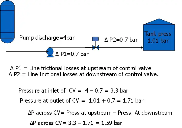
Cv Calculation for Control Valve Sizing
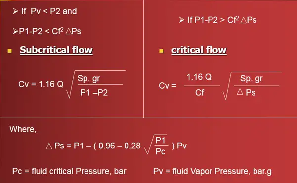
The flow coefficient or Cv is an important parameter for control valve sizing. This is also known as valve co-efficient. It specifies the number of U.S gallons of water that flows through a restriction in one minute at 60 Deg F keeping the pressure drop through this restriction is 1 psi. The Cv calculation procedure for liquid flow, gaseous/steam flow, and two-phase flow are provided below for reference.
Cv Calculation Liquid flow:
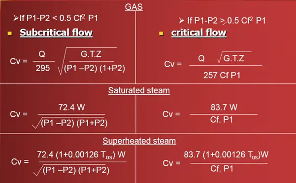
Cv Calculation Gas and Steam:
Cv Calculation Two-Phase flow:
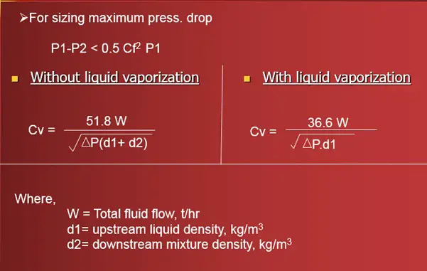
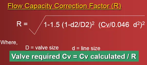
Effect of Reducers on Control Valve Sizing
- Decrease in actual valve capacity
- Creates additional pressure drop in the system
- Flow Capacity Correction Factor (R)
Thumb Rules for Control Valve Sizing
Some general thumb rules prevalent in industries while sizing control valves are:
- Assign the system and size the control valve such that:
- Pvalve = 25% system pressure drop (including control valve) or Pvalve = 1/3rd system pressure drop (excluding control valve)
- The valve is to be sized to operate between 20 to 80% open at the maximum required flow rate.
- The minimum opening should not be less than 20% at the minimum flow rate to provide a safety margin
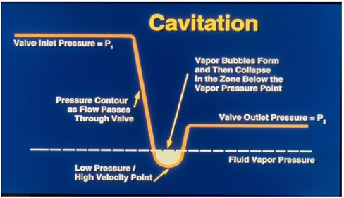
Cavitation and Control Valve Sizing
Cavitation in control valve sizing is a two-stage phenomenon:
- Formation of vapor bubbles
- Collapsing of vapor bubbles
Cavitation Phenomena:
Negative Effects of Cavitation:
- Resists the fluid flow
- Causes severe vibrations
- Erodes metal surface
- Generates high noise levels
Cavitation Countermeasures:
- Select a valve style that has a Cf value greater than required for the application
- Increase pressure upstream of the control valve by reducing elevation in the piping system
- Installation of the orifice downstream of the control valve
Flashing
Definition – Pressure at the valve outlet remains below the vapor pressure
Negative effects-Two phase flow in the downstream of control valve; Erosion
Limitations in Control Valve Performance
Noise-
- 85 dBA for process control and daily service applications
- 90 dBA for infrequent letdown and recirculation
- 5 dBA credit may be taken for insulation.
Vibration and Erosion limits
Liquid Service-
- Trim Exit vel. < 30 m/s for single-phase liquids
- Trim Exit vel. < 23 m/s for cavitating, flashing erosive services
Gas Service
- Trim Exit vel. Head > 480 kPa for continuous service
- Trim Exit vel. Head > 1030 kPa for infrequent service
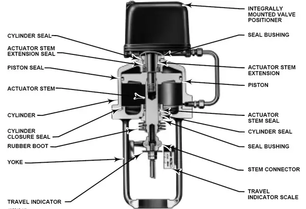
Positioner
A position controller (servomechanism) that is mechanically connected to a moving part of a final control element or its actuator and that automatically adjusts its output to the actuator to maintain the desired position in proportion to the input signal.
Control Valve Sizing Standard
Widely used control valve sizing standards are
- ISA75.01.01, Control Valve Sizing Equations
- IEC 60534-2-1
- DEP 32.36.01.17-Gen, Control valves – selection, sizing, and specification
Simplified Steps for Control Valve Sizing
The following steps can be followed for simplified Control Valve Sizing:
- STEP #1: Define a maximum allowable pressure drop for the valve
- STEP # 2: Calculate the valve coefficient (Cv)
- STEP # 3: Preliminary valve selection
- STEP # 4: Check the Cv and stroke percentage at the minimum flow
- STEP # 5: Check the gain across applicable flow rates: Gain is defined as:
- Gain = ∆ Flow / ∆ Travel; the gain should never be less than 0.50
Few more Resources for you…
Details about control valves
Ball Valve Design Features: A Literature
A brief article on Valve Inspection & Testing
An article on ROTARY SELECTOR VALVE (RSV) and MULTIPHASE FLOW METER (MPFM)
Selection of Valves: A Few Guidelines
Piping Design and Layout Basics
Piping Materials Basics
Piping Stress Analysis Basics
I like how you mentioned that when opened at the maximum flow rate, appropriate valve sizing should be operating around 20 to 80%. The manager of the warehouse I work in is thinking of getting a new solenoid control valve because he noticed the other day that our current valves weren’t working as efficiently as they used to. It seems like a good idea for my manager to think about getting equipment from a reputable company that allows the flow rate we need to operate our machinery as best as possible.
Very nice summary.
I have a question what do you mean in the rule of thumbs for control valve sizing when you you say including and excluding control valve?
How to select size of valve using CV value
IF using CV table,
Is their CV tables are diferent for different types of valves? how to get Particular CV table
Excellent work
Its a very good blog giving a lot of technical information
How we can overcome from flashing & cavitation negative effects?