
PSV or pressure safety valves (pressure relief valves) are a type of valve and are very common in any process industry. To protect any equipment from overpressure PSV systems are used in lines. When the pressure inside the system/equipment exceeds a pre-determined level (normally Set Pressure), they are activated automatically and release the pressure by popping up and bringing the equipment pressure to a safe operating level.
Two types of PSVs are extensively used in process industries:
- Open discharge PSV
- Closed discharge PSV
Are PSV Connected Systems Critical?
Due to an uncertain event if the pressure of any equipment becomes higher than the set pressure of the installed PSVs then they pop up and reduce the system pressure. During popping-up activity, the PSVs exert a huge reaction force over the system. During the analysis of PSV-connected stress systems, we have to consider this reaction force. This is the main reason that PSV-connected systems become stress-critical. The following write-up will try to explain the methods used during the analysis of such systems using Caesar II. Click here to gain in-depth knowledge about pressure relief valves.
Required Documents for Stress Analysis
The following documents are required for PRV system stress analysis using Caesar II.
- Piping isometrics.
- P&ID and line list.
- PSV datasheet with reaction force and PSV weights.
- Equipment GA and datasheet if the equipment is part of the stress system.
PSV Reaction Force Calculation & Application Philosophy
Before we start the actual analysis we should first know the reaction force. Normal practice is to obtain the reaction force from the PSV vendor or manufacturer. However if during the preliminary stage of analysis, data is not available then the reaction force for open discharge PSVs can be calculated using the below-mentioned formula (from API RP 520) for gaseous/vapor services. But later it must be corrected for forces received from the vendor.
PSV Reaction force at the point of discharge for Gas Services in lbf, F=[(W/366)* √{K*T/(K+1)*M}]+A*P
- Here, W=flow of any gas or vapor in lbm/hr
- K=ratio of specific heats (Cp/Cv) at the outlet condition
- T=temperature at the outlet in Degree R
- M=molecular weight of the process fluid
- A=area of the outlet at the point of discharge in inch^2
- P=Static pressure within the outlet at the point of discharge in psig.
- Cp and Cv=Specific heat at the constant pressure and at constant volume respectively.
For liquid services, the PSV reaction force (FR) due to the outflow of PSV (or PRV) can be calculated following the AD 2000-Merkblatt standard A2-Safety Devices against Excess Pressure (Clause 6.3.3) using the following equations (momentum theory):
PSV/PRV Reaction Force for Liquid Services in N, FR=(qm*vn/3600)
Where,
- qm=Mass flow in Kg/hr
- vn=velocity in the blowout opening=(qm*106)/(3600*ϱn*An)
- ϱn=density of the fluid in the blow-out opening at the end of the pipe in kg/m3
- An= Clear cross-sectional area at blow out end of the line in mm2
For closed-discharge PSV systems, there is no specific method to calculate the reaction force. Complex time history analysis can be used to calculate the reaction force for closed-discharge PSV systems.
Parameters Affecting Pressure Relief Valve Reaction Force
From the above equations, it is quite clear that the main parameters that affect the PSV/PRV reaction forces are:
- Mass Flow Rate: With an increase in mass flow rate the PSV reaction force increases.
- Outlet Temperature: With an increase in the PRV outlet temperature, the reaction force of the pressure relief system increases for the gaseous medium. However, for liquid medium, the PSV reaction force is not dependent on temperature.
- PSV Size: With an increase in the PSV size, the PSV reaction forces increase.
- The ratio of Specific Heats(Cp/Cv): For gas/vapor systems the increase in specific heat ratio, increases the pressure safety valve reaction force value.
- Pressure
- Fluid Density
- Velocity, etc
Applying PSV Reaction Force
The reaction force application philosophy for open discharge PSV (PSV output discharges into the atmosphere) connected systems is the same throughout the process industries. But for closed discharge, PSV connected system the force application philosophy varies from organization to organization. Some organization applies the reaction force for closed discharge PSVs but some organizations do not consider it. So users need to follow the company-specific project guidelines in such cases.
Where to Apply the PSV Reaction Force?
The following figure (Fig. 2) shows the points where the reaction force is required to be applied for open discharge PSVs.
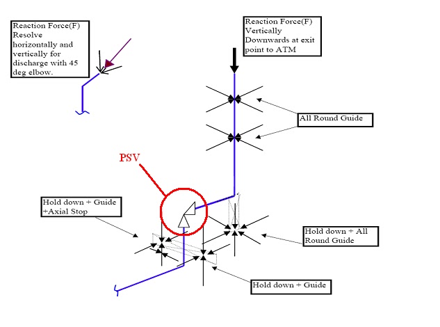
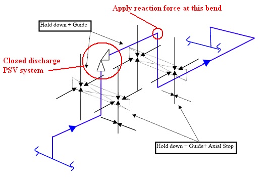
Fig. 3 shows the application point (If required) of reaction forces for closed discharge PSV connected systems.
Caesar II Load Cases for PSV Connected Systems:
PSV forces are considered occasional forces. So occasional Stress due to PSV reaction force has to be calculated and to be limited within 1.33 times Sh (As per code ASME B31.3). Here Sh=Basic allowable stress at hot conditions. Based on company practice PSV reaction force is added either with a design temperature case or with an operating temperature case. Also, some organizations have the practice of making One PSV pop up and others stand by load cases. Accordingly, make the load cases as shown below:
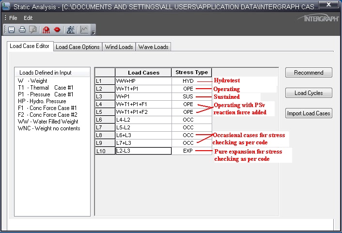
The following load cases assume two temperatures (T1= operating temperature, T2= design temperature) along with Wind and Seismic load cases:
| Load Case | Stress Type | Description | |
| L1 | WW+HP | HYD | Hydrostatic Case |
| L2 | W+T1+P1 | OPE | Operating temperature case |
| L3 | W+T2+P1 | OPE | Design temperature case |
| L4 | W+T1+P1+F1 | OPE | Operating temp+PSV reaction ( PSV 1 popping up) |
| L5 | W+T1+P1+F2 | OPE | Operating temp+PSV reaction ( PSV 2 popping up) |
| L6 | W+T1+P1+WIN1 | OPE | Operating temp+Wind from North |
| L7 | W+T1+P1+WIN2 | OPE | Operating temp+Wind from South |
| L8 | W+T1+P1+WIN3 | OPE | Operating temp+Wind from East |
| L9 | W+T1+P1+WIN4 | OPE | Operating temp+Wind from West |
| L10 | W+T1+P1+U1 | OPE | Operating temp+Seismic from North |
| L11 | W+T1+P1-U1 | OPE | Operating temp+Seismic from South |
| L12 | W+T1+P1+U2 | OPE | Operating temp+Seismic from East |
| L13 | W+T1+P1-U2 | OPE | Operating temp+Seismic from West |
| L14 | W+P1 | SUS | Sustained case |
| L15 | L4-L2 | OCC | Pure PSV Reaction |
| L16 | L5-L2 | OCC | Pure PSV Reaction |
| L17 | L6-L2 | OCC | Pure Wind |
| L18 | L7-L2 | OCC | Pure Wind |
| L19 | L8-L2 | OCC | Pure Wind |
| L20 | L9-L2 | OCC | Pure Wind |
| L21 | L10-L2 | OCC | Pure Seismic |
| L22 | L11-L2 | OCC | Pure Seismic |
| L23 | L12-L2 | OCC | Pure Seismic |
| L24 | L13-L2 | OCC | Pure Seismic |
| L25 | L15+L14 | OCC | Pure Occasional+Sustained |
| L26 | L16+L14 | OCC | Pure Occasional+Sustained |
| L27 | L17+L14 | OCC | Pure Occasional+Sustained |
| L28 | L18+L14 | OCC | Pure Occasional+Sustained |
| L29 | L19+L14 | OCC | Pure Occasional+Sustained |
| L30 | L20+L14 | OCC | Pure Occasional+Sustained |
| L31 | L21+L14 | OCC | Pure Occasional+Sustained |
| L32 | L22+L14 | OCC | Pure Occasional+Sustained |
| L33 | L23+L14 | OCC | Pure Occasional+Sustained |
| L34 | L24+L14 | OCC | Pure Occasional+Sustained |
| L35 | L3-L14 | EXP | Pure Expansion |
| L36 | L2-L14 | EXP | Pure Expansion |
Output Study:
- Check Code stresses for load cases L1, L14, and L25 to L36. It is better to keep stresses for L1 and L14 below 60% and for the rest within 80%.
- Check forces for load cases from L1 to L14.
Better Engineering Practices
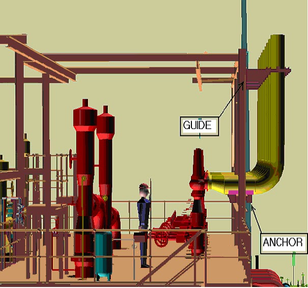
- It is a better practice to use 3-way restraints in both inlet and outlet piping of PSV-connected systems if feasible (As shown in figures 2 and 3 above). However if not possible then try to provide a 3-way restraint in the outlet only by layout modification.
- In a normal operating case Safety valve inlet line temperature will be operating temperature up to the inlet of the safety valve and the Safety valve outlet line will be in ambient temperature up to the header.
- Sometimes a Dynamic Load Factor (DLF) of 2 is used for calculating PSV reaction force.
- If any stress failure or abnormal routing changes are required, then a certain local area from the header can be used at an average temperature of 2 meters or 5D which is higher (Safety valve outlet joining at header junction point) and also shall be taken process engineer’s approval.
- If required stress engineer shall provide an R.F. pad for the trunnion-type support.
- If the connection of the PSV closed system is emerging from the header with 45˚ put SIF for this tapping. If required tapping point of the outlet line and outlet header shall be reinforced to reduce SIF.
- In case any safety valve assembly is placed on the top platform of any vessel, Support can be taken either from the top platform or support can be arranged from the top portion of the vessel taking a clip from the vessel. In both cases, the load and locations of support or clip equipment vendors must be informed through the mechanical group along with the clip information.
- Do not provide a spring below the safety valve inlet line
Few more references for you
Modelling Relief Valve (Pressure Safety Valve) Thrust force
Routing Of Flare And Relief Valve Piping: An article
Various types of pressure-relieving devices required for individual protection of pressure vessels in process plants
References:
- https://www.fem.unicamp.br/~lafer/im437/Cap03.pdf
- https://www.sciencedirect.com/topics/materials-science/stress-analysis
Online Course on PSV Piping Stress Analysis
If you still have doubts, then you can enroll in the following video course that explains the stress analysis of the PSV piping system using Caesar II software.
nice
Sir, Please indicate direction of reaction force in the bend for Closed PSV System. Also, what is the significance of inputting this reaction force on both vector1 and vector2 in the Caesar II spreadsheet. The ideas you shared are very helpful specially for us who are beginners of this field.
Dear Sir, Can you explain the below point with a diagram and other way
•In case of any safety valve assembly is placed on top platform of any vessel, Support can be taken either from top platform or support can be arranged from the top portion of vessel taking clip from the vessel. In both the cases the load and locations of support or clip equipment vendor must be informed though the mechanical group along with the clip information
Dear Sir,
Thank You for such wonderful experience. Can you upload a sample C2 file so that we can understand the animation of the system. and stress ranges.
Sir, Please indicate direction of reaction force at the bend for Closed PSV System. What is the significance of inputting this force on both vector 1 and vector 2 in the caesar2 spreadsheet. Your blogs is very helpful specially for us who are new on this field. Thanks a lot!
Sir, Please indicate direction of reaction force at the bend for PSV Closed System. Also, what is the significance of inputting this reaction force on both Vector1 and Vector2 in the Caesar II spreadsheet. Thank you for the ideas you shared to us, they are all very useful specially to us who are new in this field.
Andrew Corilla,
I feel the sign convention matches with that of CAESAR II convention. the direction of PSV outlet piping determines the direction (sign) of the force acting on the first elbow. It will be in the direction from PSV outlet towards first elbow, with CII sign convention (positive or negative)
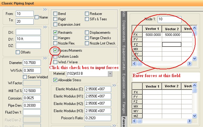
I feel that entering force values in Vector 1 and Vector 2 at the same node is not correct. It has been done only for explanation, I feel by Mr. Dey. Vector 1 corresponds to F1 and should be entered for PSV-1 pop up case at elbow-1 node.
Vector 2 corresponds to F2 and should be entered for PSV-2 pop up case at elbow-2 node.
Hope this helps. Thanks.
Please Tell how to Enter Reaction forces in classic Piping Input. How to Resolve the thrusts. May have to enter a 45 degree Bend?
please provide manual calculation for PSV,TRUNNION SUPPORT/DUMMY LEG.EXPANSION LOOP/EXPANSION JOINT.
Andrew Corilla,
I feel the sign convention matches with that of CAESAR II convention. the direction of PSV outlet piping determines the direction (sign) of the force acting on the first elbow. It will be in the direction from PSV outlet towards first elbow, with CII sign convention (positive or negative)
I feel that entering force values in Vector 1 and Vector 2 at the same node is not correct. It has been done only for explanation, I feel by Mr. Dey. Vector 1 corresponds to F1 and should be entered for PSV-1 pop up case at elbow-1 node.
Vector 2 corresponds to F2 and should be entered for PSV-2 pop up case at elbow-2 node.
Hope this helps. Thanks.
Dear Sir,
This explanation is very useful for us could you please expalin how to give the valve weight.i mean we considered two rigid to model psv so can we put the weght equally or give total weight?
yes divide the weight equally in two rigids..
Dear Sir, Please give a detailed description about where to apply reaction forces in the open and closed system, whether in the discharge elbow or in the valve itself and also describe where to provide force in the piping input in which force vector FX, FY or FZ and the sign of the vector ( +ve or -ve). Kindly provide the answer for both open and closed system.
Dear sir
if we use proper guides to the inlet piping of psv why cant we provide the springs on the inlet piping. Sometimes in the temperature range of more than 330 deg cel resting support will not work in hot sustained case so we need to provide the springs. We cant use the loops as of limitations of the pressure drop.
Dear Sir,
In open system, also input reaction force at first bend to reached last point that open to atmospheric or not ?.
In close system, also input reaction force at next bend to reached header or not ?
Dear Sir,
first of all thanks for this usefull text.
would you please explain what is diffrence between “RV. POP CONDITION” AND “ESTABLISHED FLOW CONDITION” ?
also what is diffrence between load cases for these two condition?
Hiii Sir,
Can you got info about estiblished flow condition & pop up condition
Dear Sir,
If possible, can you share sample closed loop PSV line analysis file?
This would help me lot..Please.
Closed Discharge System:
On the figure above, it is shown that the PSV reaction force must be applied on the first elbow downstream of the PSV? Why only one elbow? Should we not apply the forces on other bends as well?
Hi Anup,
what could be the application of forces in open PSV system with 2 or 3 bend from exit point to PSV. Shall we apply at all elbows. I am very much interested on “which code is describes about this force application”.
Dear sir
Thank you for good text. I have wondering the open type SRV with vent pipe. Nonmandatory appendix of ASME B31.1 shows the calculation of the force in the vent pipe. The same rule could be applied to the vent pipe or any further consideration is required?
Pls check load of L12 & L13.. Seismic load case (L12, L13 to be replaced with U2).
One comment- The API 520 equations assume sonic conditions exist inside valve body and also at exit plane, which need not be the case. Overestimation of the reaction force should be avoided.
Can I use this method to calculate the reaction force of an intermediate blocking valve on a duct that has a bypass with two vents activated by valves? thanks in advance
Can I use this method to calculate the reaction force of an intermediate blocking valve on a duct that has a bypass with two vents activated by valves? thanks in advance
Will Spring support enough for outline of PSV ?any special consideration needs to be taken during provision of Spring support in outlet line as first support from PSV outlet line experiencing high vertical movement
Psv reaction forces to be considered with Design case, because psv will not populate with operation, it will populate only when the parameters reaches close to design
Hello sir,
I saw in some PSV closed system reaction force calculation, there are two conditions 1) L7m what is reference of this conditions?