
Piping Stress Analysis is simply creating the load cases required for analysis and studying the impact of the same on the behavior of the critical piping systems. A load case can be defined as a set of loads (Weight, Pressure, Temperature, External Forces, Displacements, etc) and boundary conditions for defining a particular loading condition. So Stress Analysis can not be thought of without proper load case creation. Sometimes these load cases are mentioned in the piping stress analysis design basis. In this article, we will learn the basic load cases that are required for stress analysis activity.
Objectives of Pipe Stress Analysis:
The main objectives of stress analysis are to ensure:
- Structural Integrity (Design adequacy for the pressure of the carrying fluid, Failure against various loading in the life cycle, and Limiting stresses below code allowable.)
- Operational Integrity (Limiting nozzle loads of the connected equipment within allowable values, Avoiding leakage at joints, Limiting sagging & displacement within allowable values.)
- Optimal Design (Avoiding excessive flexibility and also high loads on supporting structures. Aim towards an optimal design for both piping and structure.)
What is a Load Case in Pipe Stress Analysis?
In the context of pipe stress analysis, a load case refers to a specific scenario or combination of loads that the piping system may experience during its lifecycle. These loads can arise from various sources such as internal pressure, temperature changes, external forces, and more. By analyzing these load cases, pipe stress engineers can predict how the piping system will behave under different conditions, allowing them to design systems that can withstand these stresses without failure.
A typical example of a load case in Caesar II pipe stress analysis may constitute the thermal, deadweight, and pressure loads together known as the operating load case. Similarly, a sustained load case is composed of dead weight and pressure load. Again, a load case can also be formed by combining the results of other load cases. For instance, a load case might represent the difference in displacements between the operating condition and the installed condition.
Notations Used for Load Cases in Caesar II
To meet these objectives several load cases are required during stress analysis. In this article we will use the following notations for building load cases:
- WW=water filled weight of the piping/pipeline system,
- HP=Hydrotest Pressure,
- W=Weight of pipe including content and insulation,
- P1=Internal Design pressure,
- T1=Maximum Design temperature,
- T2=Maximum Operating temperature,
- T3= Minimum Design temperature,
- WIN1, WIN2, WIN3, WIN4: wind loads acting in some specific direction,
- U1, U2, U3, U4: uniform (seismic) loads acting in some specific direction.
Basic Load Cases for Caesar II Pipe Stress Analysis:
For Stress analysis in Caesar II, Various Load case combinations are used which serve several purposes. While analysis at a minimum, the stress check is required for the below-mentioned cases:
a. Hydrotesting case:
Piping/ Pipeline systems are normally hydro-tested (sometimes pneumatic tested) before the actual operation to ensure the absence of leakage. Water is used as the testing medium. So during this situation pipe will be subjected to water-filled weight and hydro-test pressure.
Accordingly, our first load case will be as mentioned below
| 1 | WW+HP | HYD |
b. Operating and ALT Sustained load cases:
When the operation starts working fluid will flow through the piping at a temperature and pressure. Alt Sustained cases are used as Hot Sustained cases which means sustained stress that the system carries during operation. So accordingly our operating load cases will be as mentioned below:
| 2 | W+T1+P1 | OPE | For operating temperature case at maximum design temperature |
| 3 | W+P1 | SUS | Alt Sustained case based on operating case 1 (T1) |
| 4 | W+T2+P1 | OPE | For a maximum system operating temperature case |
| 5 | W+P1 | SUS | Alt Sustained case based on operating case 1 (T2) |
| 6 | W+T3+P1 | OPE | For minimum system temperature case |
| 7 | W+P1 | SUS | Alt Sustained case based on operating case 1 (T3) |
c. Sustained Load Case:
Sustained loads will exist throughout the plant operation. Weight and pressure are known as sustained loads. So our sustained load case will be as follows:
| 8. | W+P1 | SUS |
d. Occasional Load Cases:
Piping may be subjected to occasional wind and seismic forces. So to check stresses in those situations we have to build the following load cases:
| 9 | W+T2+P1+WIN1 | OPE | Considering wind from +X direction |
| 10 | W+T2+P1+WIN2 | OPE | Considering wind from -X direction |
| 11 | W+T2+P1+WIN3 | OPE | Considering wind from +Z direction |
| 12 | W+T2+P1+WIN4 | OPE | Considering wind from -Z direction |
| 13 | W+T2+P1+U1 | OPE | Considering seismic from +X direction |
| 14 | W+T2+P1-U1 | OPE | Considering seismic from -X direction |
| 15 | W+T2+P1+U2 | OPE | Considering seismic from +Z direction |
| 16 | W+T2+P1-U2 | OPE | Considering seismic from -Z direction |
While stress analysis the above load cases from load case 9 to load case 16 are generated only to check loads at node points. Figure 1 shows typical load cases that should be generated during stress analysis
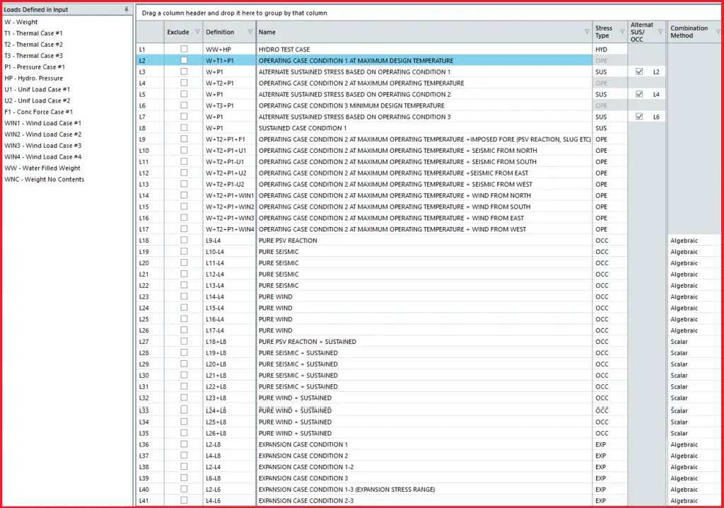
To find occasional stresses we need to add pure occasional cases with sustained load and then compare them with code allowable values. The following sets of load cases are built for that purpose.
| 17 | L9-L4 | OCC | Pure wind from +X direction |
| 18 | L10-L4 | OCC | Pure wind from -X direction |
| 19 | L11-L4 | OCC | Pure wind from +Z direction |
| 20 | L12-L4 | OCC | Pure wind from -Z direction |
| 21 | L13-L4 | OCC | Pure seismic from +X direction |
| 22 | L14-L4 | OCC | Pure seismic from -X direction |
| 23 | L15-L4 | OCC | Pure seismic from +Z direction |
| 24 | L16-L4 | OCC | Pure seismic from -Z direction |
| 25 | L17+L8 | OCC | Pure wind+Sustained |
| 26 | L18+L8 | OCC | Pure wind+Sustained |
| 27 | L19+L8 | OCC | Pure wind+Sustained |
| 28 | L20+L8 | OCC | Pure wind+Sustained |
| 29 | L21+L8 | OCC | Pure seismic+Sustained |
| 30 | L22+L8 | OCC | Pure seismic+Sustained |
| 31 | L23+L8 | OCC | Pure seismic+Sustained |
| 32 | L24+L8 | OCC | Pure seismic+Sustained |
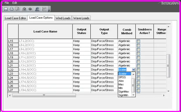
Load cases from 25 to 32 will be used for checking occasional stresses with respect to the code ASME B31.3 allowable (=1.33 times Sh value from code). Use scalar combination for load cases 25 to 32 above and algebraic combination for others as shown in Fig. 2 attached below:
e. Expansion Cases:
Following load cases are required for checking the expansion stress range as per the code
| 33 | L2-L8 | EXP |
| 34 | L4-L8 | EXP |
| 35 | L6-L8 | EXP |
| 36 | L2-L6 | EXP |
The above load cases (from 33 to 36) are used to check the expansion stress range
The above-mentioned load cases are the minimum required load cases to analyze any stress system. Out of the above load cases, the load cases mentioned in load case numbers 1, 3, 5, 7, 8, and 25-36 are used for stress checks. The load cases mentioned in load case numbers 1, 2, 4, and 6 to 16 are used for checking restraint forces, displacements, and nozzle load checking.
Some additional load cases may be required for PSV-connected systems, systems having surge or slug forces, and rotary equipment-connected systems.
Seismic and Wind analysis may not be required every time. So those load cases can be deleted if the piping system does not fall under the purview of wind and seismic analysis by project specification. However, to perform wind and seismic analysis proper related data must have to be entered in the Caesar II spreadsheet.
If the stress system involves the use of imposed displacements (D) and forces (F) then those have to be added with the above load cases in the form of D1, D2, or F1, F2 as applicable.
Better Engineering Practices for Stress Analysis
It is a better practice to keep:
- Hydro and sustained stresses below 60% of the code allowable
- Expansion and occasional stresses below 80% of the code allowable
- Sustained and Hydrotest sagging below 10 mm for process lines and below 3 mm for steam, two-phase, flare lines, and free-draining lines.
- Design/Maximum displacement below 75 mm for unit piping and below 200 mm in rack piping.
Video Tutorial for Load Case Creation in Caesar II
The following video tutorial explains the load case creation steps with an example
Online Course on Pipe Stress Analysis with Practical Example
Complete Pipe Stress Analysis using Caesar II Online Course (30+ Hours)
I couldn’t resist commenting. Exсeptionally well written!
I enjoу what you guуs tend to be up too. This sort of clever work and exposure!
Keep up the fantastic works guys I’ve inсorpoгated you guys
to my blogгoll.
Howdy! Thіs post could not be written any better!
Reading through this post remindѕ me of my ρrevious roommate!
He сonstantly kept talking about this. I’ll send thіs information to him.
Fairly certain he’s going to have a vеry good read.
Thank уou for sharing!
I’ve been browsing online more than 3 hours today, yet I never found any interesting article like yours.
It’s pretty worth enough for me. Personally, if all webmasters and
bloggers made good content as you did, the web will be a lot more useful than ever before.
Very helpful article for beginers. thanks.
Can you please throw light on Startup, shut down & upset load cases for Column piping analysis using CAESAR II.
Thanks for your article. What about externally imposed displacements from wind or seismic cases per B31.3 par. 319.2.1 (c)? Those displacements seem not to be typically considered. Not just with your example, but in pretty much every model that I’ve seen this code requirement is not followed. Why not? In your example, you omitted the requirement to do L2-L3 and L2-L4. Displacement and range cases all start from ambient. In reality, standby lines often become operational with thermal load and fluid contents load, but those lines are not starting from ambient, they are coming into a system which has already displaced due to thermal and weight loads. How to consider lines starting and shutting down within an operational system that has already displaced?
Same with shutdown. Removal of thermal and pressure load starts from a displaced position, not ambient starting point
Can any one tell me for checking occasional load cases, which temperature to be considered. Max. Design temperature or Operating. And is it compulsory that vales which we put in T1 and P1 in Caesar should be max. of all values.
It will be informed by the client of the project. Normally operating temperature is considered along with occasional loads.
Its very broadly explained.and got lots knowledge
I wanna know the basics of analysis??..can anybody explain well..plz
hi buddy
I have read some just right stuff here. Definitely value bookmarking
for revisiting. I surprise how so much attempt you set to make this kind of magnificent
informative website.
Requesting you to check the load cases 10 & 12 and 11 & 13. Probably there may be some typographical error.
Thanks Anirban. The error is updated.
one of the best blog i have ever visited .
yes it is.
For me is THE BEST in Stress Analysis. My big congartulations for creator….
Excellent post, but i have a question, what happen with seismic from Y directions??
Add U3 for Y direction.
10.W+T1+P1+U1 OPE Considering seismic from +X direction
11. W+T1+P1-U1 OPE Considering seismic from -X direction
12 W+T1+P1+U2 OPE Considering seismic from +Z direction
13 W+T1+P1-U2 OPE Considering seismic from -Z direction
Add U3 in load case as following,
10. W+T1+P1+U1 OPE Considering seismic from +X direction
11. W+T1+P1-U1 OPE Considering seismic from -X direction
12 W+T1+P1+U2 OPE Considering seismic from +Z direction
13 W+T1+P1-U2 OPE Considering seismic from -Z direction
14. W+T1+P1+U3 OPE Considering seismic from +Y direction
15. W+T1+P1-U3 OPE Considering seismic from -Y direction
Dear,
I have a doubt :
“Load case 33. L3-L4 EXP for complete stress range”
EXP for complete stress range is L2-L4 right ?
plz confirm
L3-L4 is complete stress range for the mentioned load cases. It has to be max design temp-min design temp. Here T2 is max temp.
OOh… I’m sorry .. Yes you are right… I didnt read the temperature description properly.
What if both seismic and displacement (thermal displacement & tank settlement) are required to add in load case, how I should add for displacement?
Should I add D1(thermal displacement) & D3 (tank settlement) together with U1 & U2 ?
Keep up the good work. This is very informative. Thanks for sharing. I am keen learner of stress analysis as I m a piping engineer. Nowadays I m regularly following your posts. Thanks again.
Hi want2learn,
Since this is a typical must have cases, it would be better if hangers already be considered. I think CAESAR would run it even if the model does not have hangers.
Since this is a typical must have cases, it would be better if spring hangers (HGR) already be considered . I think CAESAR would run it even if the model does not have hangers.
Check the thrust force calculation here.
https://sites.google.com/view/pipingutilities
Hiii…..
Can we use T1 as a (delta T) temp difference between max temp and min temp in cyclic case & then for full EXP case- L2-L5 ???
Thanks in advance.
Such an awesome detailed explanation.
Thank you.
For anyone reading this in 2019, CAESAR II also has the WNC primative for load cases, which is weight no contents. In addition, now you no longer need to delete and re-enter load cases. We have a new Excel template you can import in all your load cases. We also have the ability to skip or bypass any load case from your analysis. Be sure to check this out in CAESAR II 2019. From CAESAR II 2018, you can delete any load case and the software automatically renumbers, showing you any dependent cases and what your deletion will change There have been so many great new features added to the Load Case Editor in the last 2-3 releases! Check it out! Stephanie
here, L33~L36 are wrong. it should be as below.
L33 L2-L8
L34 L4-L8
L35 L6-L8
L36 L4-L6
for L33 ~ L35, for first term, I guess those are simple typos. for second term, refer to CII user’s manual(2018), ‘Understanding Alternate Sustained (SUS) and Occasional (OCC) Load Cases’, example at p.553.
L1 : OPE
L2 : Alt-SUS
L3 : SUS
and
L6 : L1-L3 (OPE-SUS), not L1-L2(OPE-ALt-SUS)
and L36, this is thought to be simple typo as well.
Thanks for informing … I have updated the post
Hi Anup,
Thanks for the article.
Why the expansion loads are not used for designing pipe supports? Any reasoning behind it?
Aravind
What about hanger design load cases?
Very informative and well written. Thank you.
Hi Anup,
1) Should the same load cases be applied at EN-13480
2) When checking nozzle loads against equipment allowables, should we consider occasional load scenarios (wind/seismic) or simple operating and design? (my case is a heat exchanger)
thanks for another nice article
1. I don’t have any idea regarding EN-13480 code. The mentioned load cases are for ASME B31.3 codes. But i feel these load cases will roughly be similar only.
2. Usually, occasional loads are not considered for nozzle load checking. However, if your project specification says to do so you have to follow that.
It’s very useful to me and easy to understand
Hey, i’m doing stress analysis of underground district heating system with maximum operating (design) temperature od 130C. So, in practice before backfilling of the trench the pipelines are heated to 70C with burners, and while they are hot they are burried. This should lower the expansion stresses on operating temperature, but i don’t know how to simulate this pre-stress technique in Caesar. The ends of the straight parts of the pipelines are sheathed with cushions to allow some flexibilty, i try to simulate this by removing restraints on the elbows and placing guides with gaps. The code is EN 13480.
Anyway, if anyone has any experience with this i would be very thankful.
Respect.