
Hopefully, all of you have gone through my post on Methods for checking flange leakage. In that article, I mentioned the theoretical background (analysis criteria, the basic theory behind flange leakage checking, analysis methodology, etc.) for checking flange leakage. So click here to refer to the article once again before you proceed with this article. In this current write-up, I will explain the step-by-step method for performing flange leakage analysis methodology following the Pressure Equivalent Method using Caesar II. Click here to learn the ASME Section VIII method.
Caesar II methodology for Pressure Equivalent method
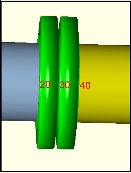
Model the complete stress system from the stress isometric. It’s preferable to model each flange separately for analysis. For valve assembly, model the flanges and valves separately. Once the modeling is complete select the flanges that need to be analyzed as per the pressure equivalent method. In Fig. 1, nodes 20-30 and nodes 30-40 denote the flange assembly. Node 30 is the interface point of both flanges where flange leakage checking is required.
Inputs for Flange Analysis
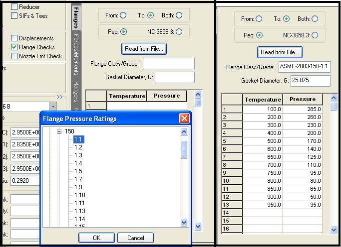
Now refer to Fig. 2 provided below. Click on the Flange checks button (Checkbox) which will activate the flange input module of the Caesar II Input Screen. Now select the Flange Node(From/To/Both) and Calculation Type as shown in Fig. 2. From/To to be selected such that node 30 as mentioned above is selected in the model. For example, as node 30 is the interface point, “To” need to be selected in element 20-30 and “From” to be selected for element 30-40. Both are normally selected for flanged valves keeping the valve active. As we are performing the Pressure Equivalent method, Peq needs to be selected.
Next, Select Flange Class/Grade through the ‘Read from File’ button and refer to ASME B 16.5/ ASME B 16.47 material tables. Select flange pressure class and material grade along with governing ASBE B 16.5 code with year.
Required data will automatically be filled in. By default, the value of G will be taken as the mean gasket diameter. Users can cross-check and update the value of G as per ASME B 16.20 & ASME Sec. VIII Div. 1, Appendix 2, Table 2-5-2. based on the following equation:
- b0 = 1/4, G = Mean diameter of the gasket contact face
- b0 > 1/4, G = Outside diameter of gasket contact face less 2b, b=basic gasket width from code. check the above-mentioned code table for more details.
Flange Leakage Checking Setting and Output Result
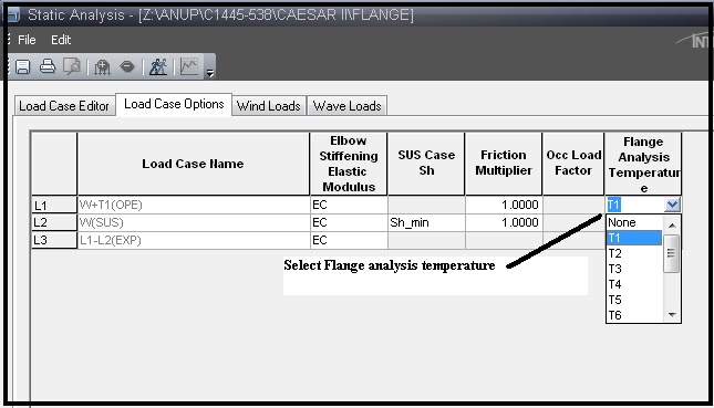
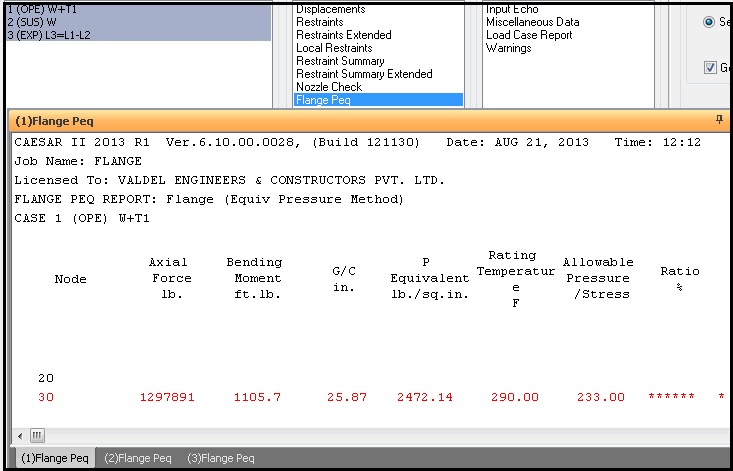
Now go to the load case editor of Caesar II and select the temperature at which flange leakage checking is to be performed as shown in Fig. 3. Normally, flange leakage is performed at the maximum design temperature. So, select that temperature. Now run the analysis to check the results. In case the calculated flange stress exceeds the allowable results will be shown in red color. The report will show the % ratio of the calculated equivalent pressure with respect to allowable. Check Fig. 4 for output results.
Dear Sirs,
Thank you for this reference, as currently I am calculating this Pe using caesar but why caesar using force perpendicular to my axis instead of axial force, let say my piping is in z direction (as axial = Fz) but caesar using force Fx for this calculation?
Thanks
Hi Anup
When i model a valve or flange use Cadworx database, the dimension and weight of valves/flange different with vendor data. How can I create an other databases for valves/flange or modify the database of Cadworx (I modify the cadworx catalog in C:\ProgramData\Intergraph CAS\CAESAR II\5.30 but the dimension and weight of valves/flange didn’t change in model)
sir,
what is main different between in static analysis and dynamic analysis?
Dear Sir/Madam
your website is so informative and I appreciate it.
in this article figures 2~4 have not loaded and I was wondering if you could send me these figures.
thank you in advance.
AZ
The figs 2 to 4 referenced above are not visible.
GRP piping and metal lap-joint flange check
i have a GRP system and lap-joint flanges (metal flanges and GRP stub-end).
The flanges connect the two stub-ends and between every couple of metal flange there are the two GRP stub-end ends, so metal flange don’t connect direcly, there is GRP between them.
How to perform flange check in this situation?
thank you
Any thoughts about API Flange Checks?
API flange checks are done using the respective code…Mostly API 6AF…They have allowable axial force, and bending moment curves with respect to pressures…Your calculated values have to be within those curve values..