
Types of Mechanical Draft Cooling Towers
- The forced draft is a mechanical draft (Fig. 1) tower
- blower type fan at the intake
- Fan forces air into the tower, creating high entering and low exiting air velocities.
- Induced draft, a mechanical draft tower
- with a fan at the discharge which pulls air through the tower
- fan induces hot moist air out the discharge
- low entering and high exiting air velocities, reducing the possibility of recirculation in which discharged air flows back into the air intake
- Two configurations, Cross Flow and Counter Flow
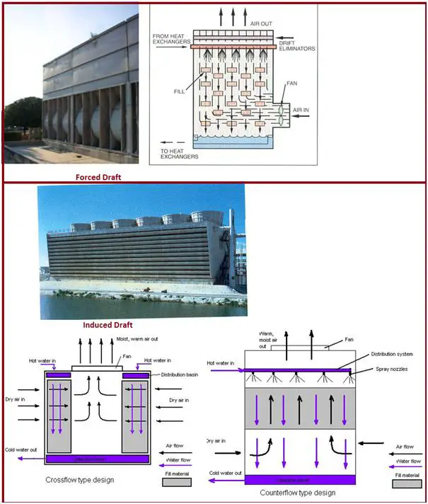
Cross Flow Induced Draft Cooling Towers
- Airflow directed perpendicular to the water flow
- Airflow enters one or more vertical faces of the cooling tower to meet the fill material
- Air continues through the fill and thus past the water flow into an open plenum area
- Water flows (perpendicular to the air) through the fill by gravity
- Gravity distributes the water through the nozzles uniformly across the fill material
Counter Flow Induced Draft Cooling Towers
- The airflow is directly opposite of the water flow
- Airflow first enters an open area beneath the fill media and is then drawn up vertically
- The water is sprayed through pressurized nozzles and flows downward through the fill, opposite to the airflow
Advantages of Cross Flow Towers
- Low pumping head, lower first cost pumping systems
- Lower energy and operating costs
- Accepts larger variation in water flow without adverse effect on the water distribution system
- Easy maintenance access to distribution nozzles
- Low static pressure drop
- Reduced drift, less make-up
- More air per fan horsepower
- Large diameter fans can be used so that fewer cells are required for a given capacity
- Due to more fill gap choking is minimized
- Cost lower than counterflow
Disadvantages of Cross Flow Towers
- Larger footprint
- Approach to cooling tower limited to 4 deg C
- The icing of louvers during cold weather, Larger louver surface area makes icing more difficult to control
- Low-pressure head on the distribution pan may encourage orifice clogging and less water breakup at the spray nozzle
Advantages of Counter Flow Towers
- Increased tower height accommodates longer ranges and closer approaches (can be less than 4 deg C)
- More efficient use of air due to finer droplet size from pressure sprays
- Vertical air movement across the fill allows the coldest water to be in contact with the driest air maximizing tower performance
Disadvantages of Counter Flow Towers
- Cost higher than Crossflow tower
- Height is more
- Increased system pumping head requirements
- Increased energy consumption and operating costs
- Difficult to inspect and clean distribution nozzles
- Requires individual risers for each cell, increasing external piping costs
- Fill gap is less so choking is possible
- Resistance to upward air travel against the falling water results in higher static pressure loss and a greater fan horsepower than in crossflow towers
- Restricted louver area at the base with the high velocity of inlet air increases the fan horsepower
- The tendency for uneven distribution of air through the fill with very little movement near the walls and center of the tower
- High inlet velocities are liable to suck airborne trash and dirt into the tower
When to choose – Crossflow towers?
- To minimize pump head
- To minimize pumping and piping first costs
- To minimize operating costs
- When flow variance is expected from the process
- When ease of maintenance is a concern
When to choose – Counterflow towers?
- When space (footprint) is a concern
- When icing is of extreme concern
- When pumping is designed for additional pressure drop
Material Balance of Cooling Towers
- A water balance around the entire system is: M = E + B + W (where, E = Evaporation, B = Blowdown and W = Windage losses, in m3/hr)
- Evaporation Losses, E = {C X (T1- T2) X Cp} / Hv (where, C = amount of circulating water in m3/hr, T1/T2 = return/supply temperature, Cp = specific heat of water and Hv = latent heat of vaporization of water)
- Windage or drift losses, W from large-scale industrial cooling towers, in absence of manufacturer’s data, may be assumed to be:
- W = 0.3 to 1.0 percent of C for a natural draft cooling tower without windage drift eliminators
- W = 0.1 to 0.3 percent of C for an induced draft cooling tower without windage drift eliminators
- W = about 0.005 percent of C (or less) if the cooling tower has windage drift eliminators
- Since the evaporated water has no salts, a chloride balance around the system is: M (Xm) = B (Xc) + W (Xc) = Xc (B + W) where, M = Make-up quantity in m3/hr, Xm = concentration of chlorides in make-up water in ppmw and Xc = concentration of chlorides in circulating water in ppmw.
- Xc/Xm = Cycles of concentration = ppm chloride in circulating water/ppm chloride in make-up water = M / (B+ W) = M / (M – E) = 1 + { E / (B + W) }
- Lower COC means high operating cost due to higher make-up
- As the cycles of concentration increase the water may not be able to hold the minerals in solution, once solubility is exceeded, they precipitate and cause fouling in exchangers
- Cycles of concentration vary from 3 to 5 depending upon the make-up water quality
Components of a Cooling Tower
- Cooling Tower Hot Water distribution system – The collection header and branch headers to the individual cells via flow control valves
- Cooling Tower Fans – with on-off, dual speed, variable speed motors
- Cooling Tower Fill, Louvers and Drift Eliminators – Each fill sheet has louvers and drift eliminators
- Cooling Tower Cold Water Basin – Screens, Sluice gates, pump suction lines
- Types of pump used – Horizontal Centrifugal, Vertical turbine
- Fill, the heat transfer surface, most important component of a cooling tower
- The efficiency of the tower depends upon its ability to promote both the maximum contact surface and the maximum contact time between air and water
- Two basic types of fill – Splash type and Film type
- In crossflow, either type can be applied but in counterflow, through either type can be used but tends toward almost exclusive use of the film fills
Material of Construction of Cooling Towers
- Wood: Available, Workable, Low Cost, and Durable.
- Metals: Steel, Cast Iron, copper alloys, and aluminum alloys. Special care required for corrosion control for metals other than steel. Used for fan hubs, basins, partitions, fan cylinders, bolts, nuts, washers, gear cases, anchor castings, etc.
- Plastics: Capable to be molded into single parts of complex shape and dimensions. Used for fan blades, fan cylinders, fill supports, drift eliminators, louvers, etc.
- Concrete: Higher initial cost but decreased fire risk and higher load-carrying capacity.
Special Types of Cooling Towers
- Dry Cooling Towers
- Hybrid Cooling Towers (also called plume abatement towers)
Dry Cooling Towers
- Basically an air-cooled heat exchanger
- Sensible cooling of water through finned coils
- The low temperature of inlet air is essential
- Less efficient cooling – large surface areas
- Water temperatures higher than evaporative type cooling towers
Hybrid Cooling Towers
- Combines both dry and wet sections
- Operational flexibility in case of variation in ambient conditions
- More effective cooling than dry type towers
- Avoids plume formation
Hybrid Cooling Towers-Sub Types
- Parallel path tower
- Series path tower
- Adiabatic air pre-cooler
Parallel Path Towers (Fig. 2):
- Coil section located vertically on top of the fill section
- Induced draft fan
- Hot water flows through the coil and fills section in series
- Parallel streams of airflow through the coil and fill sections
- Dry and saturated air streams mix in the fan section
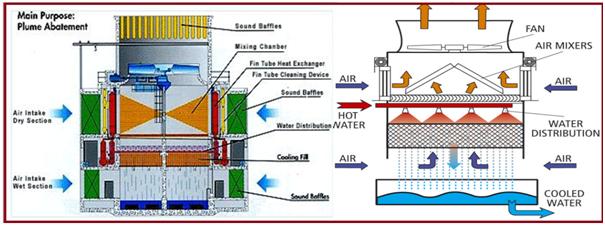
- The ratio of two sections depending on the inlet air characteristics
- Supply of air to each section may be adjusted with louvers at the inlet
- During low ambient temperatures fill section may be completely isolated
- Requires more height of the tower
Series Path Tower:
- Air flows through the coil and fills sections in series
- Induced draft fan – cross flow
- The coil may be before or after fill section
- De-saturation of the air stream in the coil section
- Less height of tower compared to parallel path towers
- Less flexibility of operation on airside
- The proximity of the dry coil to fill section leads to:
- Impingement
- Scaling problems
- Restricted airflow.
Adiabatic Air Pre-Cooler (Fig. 3):
- Also known as a humidified air cooler
- Effective for low RH areas
- Fill section adjacent to dry section with drift eliminator in between
- Finned tube bundle located on top of dry section
- The induced draft fan draws air through fill and coil sections in series
- Two water streams – closed loop through the coil and open loop through the fill
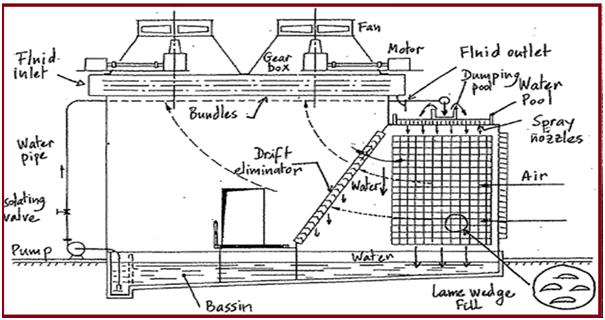
- Water re-circulated infill section
- Air, cooled in the fill section, exits in the saturated condition
- Process water-cooled in the coil with outlet air from fill section
- Air at the outlet of coil section exits at a higher temperature and in unsaturated condition
- Water circuit in an open loop can be shut-off during winter
- Less impingement
- Existing evaporative towers can be retrofitted
Disadvantages:
- Two water circuits mean additional accessories and chemical treatment
- Overall space requirement increases
Comparison of Hybrid and Evaporative Towers
Hybrid towers have:
- Fewer problems of water loss
- No plume formation
- More flexibility in operation
- Bigger sizes
- More accessories
- Higher fan powers
Required Float valve design feture if avialable please.
Extremely very useful tips for us!!! very inciteful. I’m just leaving the comment to appreciate your efforts in disseminating the knowledge. …Thanks for the share!