Process Design of Centrifugal Compressor System

Process Datasheet

  • Defines the suction and discharge conditions (Pressure, Temperature, Flowrate) and gas composition.
  • The main input to the compressor vendor.
  • Define all possible options of suction and discharge conditions and gas compositions, present, and future.
  • The vendor selects the model which fits these conditions the best.

Compressor performance curves

  • Input from the compressor vendor
  • Relationship of Flow vs. Head (polytropic, isentropic)
  • Surge point and choking (stone wall)
  • Variation with RPM
  • Input to HYSYS for the generation of performance at different conditions

Performance data

  • Input from compressor vendor.
  • Defines the interstage pressures and temperatures.
  • Gives input for the HYSYS simulation.

Process Simulation

  • HYSYS simulation model
  • Based on the Compressor performance data
  • Forms the basis for material and energy balance.
  • Defines the cooler heat duty.
  • Generates property data for the calculations.
An example of typical process simulation
Fig. 1: An example of a typical process simulation

System components

Typical system components
Fig. 2: Typical system components

Advantages Seal gas system

  • No seal oil system required
  • No need to dispose of/clean up contaminated oil
  • Eliminates fouling problems due to oil ingress in process streams
  • Less gas loss
  • The dry gas seal advantages significantly outweigh the seal oil benefits

Process Calculations

  • Settle out Calculations
  • Blowdown calculation
  • Pipe sizing calculations
  • Hydrate calculations

Settle out calculation

  • Equalized pressure during a compressor shutdown.
  • High-pressure trip conditions are taken as pressures before settling out.
  • Enthalpy balance of the system.
  • It can be done using a spreadsheet or HYSYS.
  • It can define the design pressure for some of the sections.
READ  Magnetic Particle Inspection (MPI) Procedure

Blowdown calculation

  • Intent: Reduce the pressure of the equipment to 50% of the design pressure within 15 minutes during a fire emergency.
  • Typically done using Dynamic depressurizing Utility in HYSYS
  • Relief valves are not depressurization devices.
  • Ball valve + Orifice combination OR control valve

The blowdown calculation takes the following into account:

  • Vaporization of liquid due to pressure reduction,
  • Vaporization due to heat input from the external fire,
  • Pressure after 15 minutes is reduced from design pressure to 50% of design pressure,
  • Start at settle-out conditions.
  • The gas compressor system is blocked in and no additional mass is fed into the system during blowdown.
  • Maximum allowable depressurization rate for the compressor O-rings of 20 bar/min,
  • There is no other heat input into the system other than fire.
  • The relief rate calculated is not limited by the flare.
  • Use to find the lowest temperature attained and hydrate formation possibilities.
  • Uncontrolled vs. Staged Blowdown
Uncontrolled vs. Staged Blowdown
Fig. 3: Uncontrolled vs. Staged Blowdown

Pipe sizing calculations

  • Importance of pressure drop and machine performance.
  • Tools used.
  • Cooler header sizing.
  • Avoiding loops in suction.
  • Provision of drain boots.

Hydrate calculations

  • Hydrates are ice-like non-stoichiometric crystal structures composed of water molecules engaging natural gas molecules.
  • The solid formation chokes piping.
  • Flow problems.
  • The formation depends on P, and T conditions and composition.
  • Predicted by HYSYS.

Gas Blow-by calculations

  • Caused by losing liquid level in the scrubbers.
  • High-pressure gas flows into the low-pressure system potentially overpressurizing it.
  • Calculations are done to ensure that the downstream system is adequately protected.
  • The control valve is considered to be fully open during this case.
  • The highest operating pressure of the upstream system is considered for sizing.
READ  What is an Air Relief Valve, Air Release Valve, or Air Valve?

Scrubbers

  • Vertical Knock out vessels.
  • Limit liquid carries over to the compressors.
  • Internals – SMS / SV / SVS

Air Coolers

  • Heat duty based on Process Simulation.
  • Process parameters based on the simulation.
  • The vendor does the sizing with HTRI or other proprietary software.
  • Pressure drop is critical.

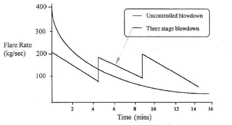
Flare and Blowdown system

  • The flare system needs to be designed for
  • Blowdown depressurizing load.
  • Flaring due to compressor trip
  • Fire case relief
  • Blocked discharge of the compressor
  • The flare system may require a KOD based on the quality of the gas flared. (Liquid presence)

Control Philosophy

  • Capacity control
  • Antisurge control
  • Scrubber level control

Safeguarding philosophy

  • Process shutdown.
  • Emergency shutdown.
  • Other shutdowns.

Process shutdown

  • Close the discharge ESD valve. The suction ESD valve shall remain in an open position. The blowdown ESD valve shall remain in a closed position. The antisurge valves and capacity control valve goes to the open position. The motor stops and the compressor settles out to suction pressure. The auxiliaries keep running.
  • Generally initiated on trips on process parameters.
  • Enables faster start-up compared to ESD

Emergency shutdown

  • PSD1 shall Trip the compressor motor & auxiliaries, and Close the ESD valve on the suction and discharge header.
  • The antisurge valves and capacity control valve goes to the open position.
  • The external seal gas supply shall be isolated by the ESD valve on the seal gas line.
  • The compressor blowdown valves shall open and depressurize the gas to flare.
  • Initiated on Fire, Station ESD.
READ  Electrical Submersible Pumps: Working Principle, Components, Installation, Maintenance, Applications

Other shutdowns

  • The suction, inter-stage(s), and discharge scrubbers low-level close liquid outlet ESD valves.
  • The inter-stage(s) and After-cooler fan high vibration shall trip the respective fan.
  • Low temperature at the aftercooler outlet shall trip the first working fan at 30 deg C and the next at 20 deg C.
  • External seal gas high pressure downstream of external seal gas pressure letdown valve for LP casing shall close the external seal gas supply ESD valve.

Few more useful resources for you…

Articles related to Compressor
Articles Related to Pumps
Piping Design and Layout Basics
Piping Stress Analysis Basics
Piping Materials Basics
Articles Related to Mechanical Design
Articles Related to Process Design
Articles Related to Heat Exchanger

Anup Kumar Dey

I am a Mechanical Engineer turned into a Piping Engineer. Currently, I work in a reputed MNC as a Senior Piping Stress Engineer. I am very much passionate about blogging and always tried to do unique things. This website is my first venture into the world of blogging with the aim of connecting with other piping engineers around the world.

One thought on “Process Design of Centrifugal Compressor System

  1. In the Air Cooler suction another important thing is calculating AIR RECIRCULATION (amount of air NOT used during heat transfer). Secondly I would like the post rewritten for PD compressors like those used for Chlorine (liquid-ring)

Leave a Reply

Your email address will not be published. Required fields are marked *

Recent Posts