
Piping Stress Analysis is the most important activity in Piping Design. Once, pipes are routed following design guidelines, they need to be verified by piping stress analysis to ensure they will work smoothly throughout their design life. This article will explain the basic points for Piping Stress Analysis. Piping Stress Analysis is also termed Piping Flexibility Analysis.
What is Pipe Stress Analysis?
Pipe Stress Analysis is an engineering activity that focuses on evaluating the stresses, deformations, and forces within a piping system. It plays a vital role in ensuring the safe and reliable operation of piping systems in various industries, including oil and gas, petrochemical, power generation, and more.
Objectives of Pipe Stress Analysis
Stress Analysis of Critical piping systems is performed to ensure the following objectives.
1. Structural Integrity:
- Design adequacy for the pressure of the carrying fluid.
- Failure against various loading in the life cycle. Limiting piping stresses below code allowable.
2. Operational Integrity:
- Limiting nozzle loads of the connected equipment within allowable values.
- Avoiding leakage at flanged joints.
- Limiting sagging & displacement within allowable values.
3. Optimal Design:
- Avoiding excessive flexibility and high loads on supporting structures. Aim towards an optimal design for both piping and structure.
Basic Concepts of Piping Stress Analysis
Piping Components
Pipe stress analysis considers various components like pipes, fittings, valves, and supports. Understanding the properties and behavior of these components is crucial for accurate analysis.
- Pipes: Different materials, sizes, and schedules are used for pipes, and they exhibit specific stress-strain behaviors.
- Fittings and Valves: These components introduce stress concentrations and affect the overall behavior of the system.
- Supports: Supports and restraints are essential for controlling pipe movements and distributing loads.
Load Types
Pipe systems experience several load types, including:
- Static Loads: Steady-state conditions like internal pressure, deadweight, and thermal expansion.
- Dynamic Loads: Transient events such as water hammer, relief valve discharge, and seismic activity.
- Thermal Loads: Temperature variations causing thermal expansion and contraction.
Stress-Strain Relationships
Pipe stress analysis relies on understanding the stress-strain relationship of materials. Key concepts include:
- Elasticity: Materials return to their original shape when the load is removed within their elastic limit.
- Plasticity: Beyond the elastic limit, materials deform irreversibly.
- Creep: Slow, time-dependent deformation under constant load and elevated temperature.
Governing Codes and Standards for Pipe Stress Analysis
Codes and Standards specify minimum requirements for safe design and construction (i.e. provide material, design, fabrication, installation, and inspection requirements.)
Following are the codes and standards used for Piping stress analysis of process piping:
- ASME B31.3: Process Piping Code
- ASME B31.1: Power Piping Code
- Centrifugal Pumps: API 610
- Positive Displacement Pumps: API 676
- Centrifugal Compressors: API 617
- Reciprocating Compressors: API 618
- Steam Turbines: NEMA SM23/ API 612
- Air Cooled Heat Exchanger: API 661
- Fired Heaters: API 560
- Flat Bottom Welded Storage Tanks: API 650
- Heat Exchangers: TEMA/ Vendor-Specific.
- Vessel/Column: Vendor-Specific/ ASME Sec VIII
- ASME B 31.4/ASME B 31.8: Pipeline Stress Analysis
- ISO 14692: GRE/GRP/FRP Piping Stress Analysis
- ASME B31.4: Pipeline Transportation Systems for Liquid Hydrocarbons and Other Liquids
- ASME B31.8: Gas Transmission and Distribution Piping Systems
- EN 13480: European standard for metallic industrial piping
- API 570: Inspection, repair, alteration, and rerating of in-service piping systems
Stresses in a Piping System
Types of Stress
Pipe stress analysis considers various types of stress, including:
- Axial Stress: Along the length of the pipe.
- Hoop Stress: Circumferential stress due to internal pressure.
- Radial Stress: Stress perpendicular to the longitudinal axis.
- Torsional Stress: Twisting or rotational stress.
- Shear Stress: Stress parallel to the pipe’s cross-section.
- Bending Stress: Stress due to curvature.
Sources for the generation of stress in a Piping System:
- Weight
- Internal/External Pressure
- Temperature change
- Occasional Loads due to the wind, seismic disturbances, PSV discharge, etc.
- Forces due to Vibration.
Sustained Stresses in Piping System
Sustained Stresses are the stresses generated by sustained loads. (e.g. Pressure, Weight). These loads are present continuously throughout plant life.
Resistive force arising out of sustained stresses balances the external forces keeping the system in equilibrium. Exceeding sustained allowable stress value causes catastrophic failure of the system. As per ASME B 31.3, (clause 302.3.5):
“ The sum of the longitudinal stresses, SL, in any component in a piping system, due to sustained loads such as pressure and weight, shall not exceed “Sh“. Where Sh=Basic allowable stress at the metal temperature for the operating condition being considered.
Pressure Stresses are taken care of by calculating and selecting the proper pipe thickness. The pressure thickness (t) of a straight pipe can be obtained as per ASME B31.3 from the equation (Clause 304.1.2) mentioned in Fig.1:
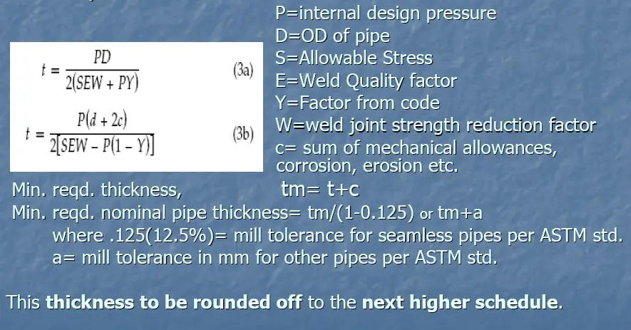
Click here to learn pipe thickness calculation in detail
Expansion Stresses in Piping System
- Change in length of a pipe of length L due to temp change (ΔT) is given by ΔL=L α ΔT Here, α =Co efficient of thermal expansion = change in length of unit length element due to unit change in temp.
- Two “α” values (denoted by A and B) in Code (Table C-1 and C-1M in ASME B31.3 Appendix C):
- The thermal Co-efficient “A” of Table C-1 denotes the mean coefficient of linear thermal expansion between 70 degrees F to the indicated temp (μin/in/0F).
- The thermal Co-efficient “B” of table C-1 denotes total linear thermal expansion between 70 degrees F to Indicated temp (unit=in/100ft).
- Table C-1M provides thermal co-efficient values in the metric system.
- Expansion stresses are generated when the free thermal growth due to temperature change is restricted. These are self-limiting or self-relenting.
Stress Intensification Factor in Piping Stress Analysis
SIF( Stress Intensification Factor): This is the ratio of the maximum stress intensity to the nominal Stress. SIF factors for different components can be obtained from Appendix D of ASME B31.3 till edition 2018. From ASME B31.3-2020 onwards Appendix D has been deleted. Now users are required to use ASME B31J or FEA for finding the values of SIF.
Equations for Calculating Expansion Stress Range and Allowable Stress Value
The displacement Stress Range due to thermal expansion is calculated based on equation SE per equation 17 from ASME B31.3( clause 319.4.4).
This SE value shall not exceed the SA value where SA= Allowable Displacement Stress Range.
As per ASME code B 31.3 (Clause 302.3.5) the allowable displacement stress range (SA) can be given by the equation (Fig.2):
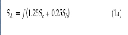
Here, f= Stress range reduction factor and Sc= basic allowable stress at minimum metal temp
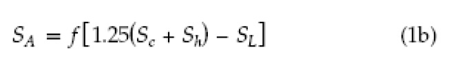
- When Sh > SL, the allowable stress range is calculated by the following equation (Fig. 3): SL=Longitudinal Stress due to sustained loads.
Occasional Piping Stresses
- Occasional Stresses are generated by occasional loads such as Wind, seismic, PSV discharge, etc.
- These loads act in a piping system for a very short period of time, usually less than 10% of the total working period.
- As per ASME B31.3, clause 302.3.6 “The sum of the longitudinal stresses, SL, due to sustained loads, such as pressure and weight, and of the stresses produced by occasional loads, such as wind or earthquake should be ≤ 1.33 times the basic allowable stress, Sh”
- The code does not explicitly explain the stresses generated due to vibration.
- The vibration problems are solved by engineering judgment and experience.
Reducing Piping Stresses
Piping stresses can be reduced by various methods like
- Providing Support at a suitable span to reduce Weight (Sustained) stresses.
- Providing Flexibility to reduce piping expansion stresses generated by thermal loading e.g. Expansion Loops, Offsets, and Inclusion of elbows to change direction.
Flexibility Analysis Requirement (as per clause 319.4.1, ASME B 31.3):
Clause 319.4.1 of ASME B31.3 states that
No formal stress analysis of adequate flexibility is required for a piping system that
(a) duplicates, or replaces without significant change, a system operating with a successful service record.
(b) can readily be judged adequate by comparison with previously analyzed systems.
(c) is of uniform size, has no more than two points of fixation, no intermediate restraints, and falls within the limitations of the empirical formula given below in Fig. 4

This means all other piping connections that do not fall in the above-mentioned group need to be analyzed. As most of the lines will not fall in any of the above groups, the numbers of lines requiring stress analysis will be huge. That is why organizations based on their experience group the lines as mentioned below and decide the method of stress analysis requirement:
Stress Criticality and Analysis Methods
- Highly Critical Lines (Steam turbine, Compressor connected lines, jacketed piping system, very high-temperature pipes, Non-metallic pipes, etc): Stress analysis is to be performed by Computer Analysis
- Moderately Critical Lines (AFC connected lines, Pump connected lines, pressure vessel connected lines, etc): Stress analysis to be done by Computer Analysis
- Low critical Lines: Visual/Simple Manual Calculation/Computer analysis and
- Non-Critical Lines: Visual Inspection
Generally, a stress-critical line list is prepared at the start of every project to understand the number of lines requiring computerized pipe stress analysis. Refer to the following article to know when a pipe stress analysis is to be performed: Stress Critical Line List or Piping Critical Line List: Definition and Basis
Basic Allowable Stress/ Pipe Material Stress
Pipe materials have defined stress limits to ensure their safety. The basic allowable stress for a pipe material is calculated as follows:
Minimum of (As per ASME B 31.3)
- 1/3rd of the Ultimate Tensile Strength (UTS) of Material at operating temperature.
- 1/3rd of UTS of material at room temperature.
- 2/3rd of Yield Tensile Strength (YTS) of material at operating temperature.
- 2/3rd of YTS of material at room temp.
- 100% of average stress for a creep rate of 0.01% per 1000 hr.
- For structural grade materials basic allowable stress=0.92 times the lowest value obtained from 1 through 5 above.
Loads on a Piping System
There are two types of loads that act on a piping system: Static loads and Dynamic Loads
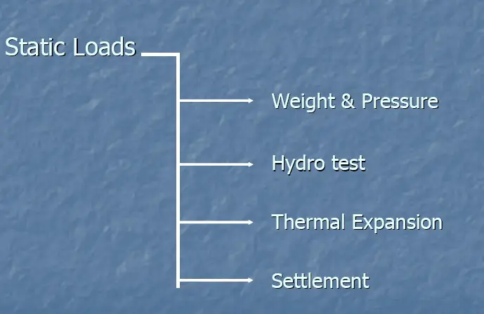
Static loads are those loads that act very slowly and the system gets enough time to react against it. Examples of static loads are shown in Fig.5
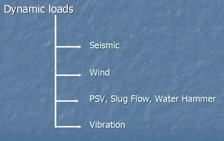
On the other hand, dynamic loads act so quickly that the system does not get enough time to react against them. Examples of dynamic loads are shown in Fig.6
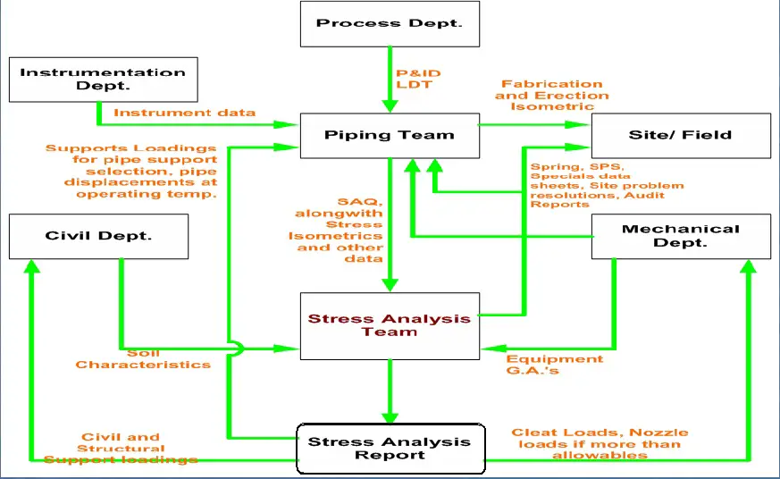
Work Flow Diagram for Pipe Stress Analysis
The interaction of the Piping Stress team with other disciplines in any organization is shown in Fig. 7:
Pipe Stress Analysis Software Programs
Here’s a list of some widely used pipe stress analysis software programs
- CAESAR II developed by Hexagon PPM (formerly Intergraph)
- ROHR2 by Sigma Ingenieurgesellschaft mbH
- PASS/START-PROF by PASS Engineering
- AutoPIPE by Bentley Systems
- ANSYS Pipe (part of ANSYS Mechanical) by ANSYS, Inc.
- Caepipe developed by SSTUSA
Among all the above, Caesar II is the most widely used piping stress analysis software package and comprehensively used worldwide. Further details about pipe stress analysis software programs are mentioned here.
Pipe Stress Analysis using Caesar II
Caesar II by Hexagon is the most popular and widely used international pipe stress analysis software. Pipe stress analysis is normally performed in four steps as listed below:
- Input Collection for Piping Stress Analysis
- Performing the stress analysis
- Interpreting the results and suggesting changes if required
- Providing Recommendations Based on Analysis
Inputs required for Piping Stress Analysis:
- Stress Isometric from Layout Group
- Line Designation Table (LDT) or Line List And P&ID from Process
- Equipment GA and Other detailed drawings from Mechanical
- Process flow diagram/datasheet if required from the process
- Piping Material Specification
- PSV/ Control Valve GA and Datasheet from Instrumentation
- Soil Characteristics from civil for underground analysis
- Nozzle load limiting Standards
- Plot Plan for finding HPP elevation and equipment orientation.
- Governing Code
Stress Analysis:
- Checking the completeness of the piping system received as a stress package.
- Node numbering on stress Iso.
- Filling the design parameters (Design temperature, Design pressure, Operating Temperature, Minimum Design Temperature, Fluid density, Material, Line Size and
thickness, Insulation thickness, density, Corrosion allowance, etc.) on stress Isometric. - Modeling the piping system in Caesar using parameters from stress Iso.
- Analyzing the system and obtaining results.
Conclusion & Recommendation:
Whether to accept the system or to suggest necessary changes in layout and support to make the system acceptable as per standard requirements.
Outputs from Stress Analysis | Stress Analysis Deliverables
The major pipe stress analysis deliverables are listed below
1. Final marked-up Isometric drawings (Stress isometrics) to Layout: The stress markup isometric consists of all the recommendations marked on the stress isometric drawing. In general, the following information is provided in stress isometric:
- Node numbers of all relevant points.
- Support Types (Rest, Guide, Line Stop, Spring Hanger, Anchor, or mix of Rest, Guide, or Line Stop Support)
- Displacements at the interface points and wherever more than the normal acceptable limit.
- Pipe routing changes if required.
- Additional support if required.
- Preliminary spring hanger details like Tag number, hot load, cold load, hydro test load, vertical maximum displacement, etc.
- Shoe lengths in case the length has to be increased from the standard length.
- Preliminary support arrangement drawing in case non-standard support is used.
- Equipment Nozzle Node Numbers.
- Trunnion Length and Reinforcement requirements, etc
- Page Continuation number
- Any special notes
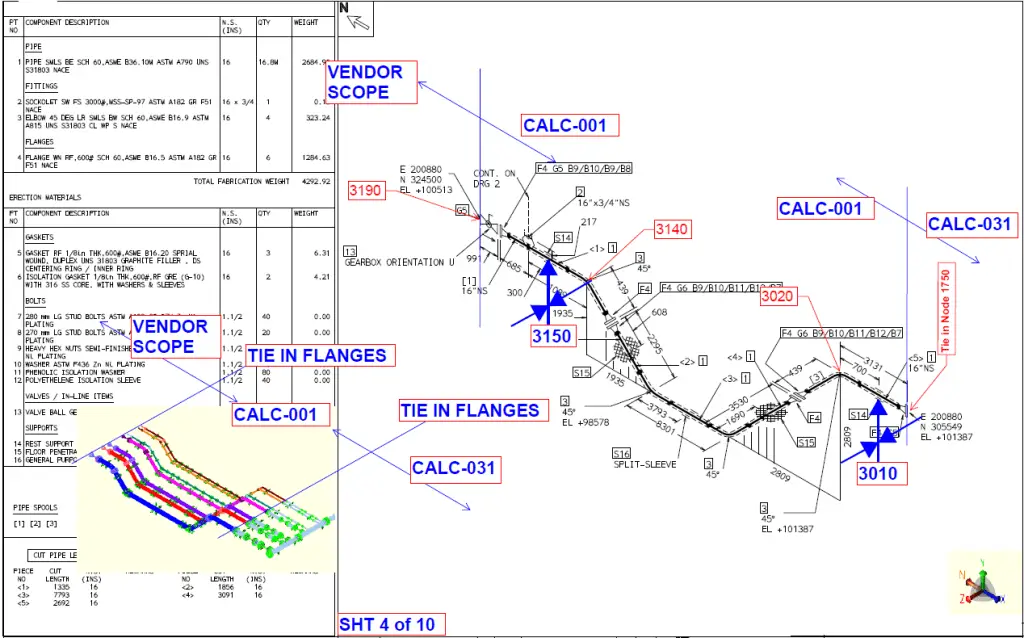
- Axis markup with respect to the north direction of isometric drawing. Refer to Fig. 8 for a typical stress mark-up isometric.
2. Support Loads to Civil for support member design: Support loads are transferred to the civil team along with the isometric markup drawing to understand the node number and support location. Usually, loads are transferred in an Excel sheet format. The different company applies different formats for providing loads to civil and structural departments. In general, the following information is provided:
- Vertical Load, Axial Load, and Lateral load in consistent units.
- A general cushion/margin is used based on project-specific criteria while providing loads.
- Notes to be considered
- In general, the loads from the following load cases are provided separately:
- Hydrotest loads
- Design temperature loads (Both maximum and minimum design temperature cases)
- Maximum of all the operating and sustained load cases (excluding occasional loads)
- All individual pure occasional loads
- Empty pipe loads
- Mention in notes that the civil team should consider the vertical load and act in a downward direction. The axial and lateral loads are to be considered to act in both positive and negative direction and the worst case will govern.
- For Hold down supports specifically provide the vertical uplift force that will act on the support.
3. Spring Hanger Datasheets for procurement
4. Datasheets for Special Supports like Sway brace, Struts, Snubbers, etc.
5. Special Pipe Support (SPS) drawings for construction
6. Stress Package final documentation for records
8. Clip or Cleat location and loading information to pressure vessel/tank vendors for their design and fabrication work.
Loads and Load Combinations for Piping Stress Analysis
Pressure Loads
Internal and external pressure loads must be accurately analyzed to determine their impact on the piping system.
Temperature Changes
Temperature fluctuations can cause significant thermal stresses, particularly in large, high-temperature systems.
Deadweight and Operating Loads
The weight of pipes, fittings, valves, and insulation contributes to the system’s overall load.
Wind and Seismic Loads
External forces like wind and seismic events must be considered in high-risk areas.
Water Hammer Effects
Water hammer, or hydraulic shock, occurs when there is a sudden change in fluid flow, resulting in pressure surges that can damage piping systems.
Pipe Stress Mitigation Techniques
Redesign
Modifying the piping layout or design to reduce stress concentrations and improve overall system performance.
Adding Supports or Expansion Joints
Introducing additional supports or expansion joints to reduce stress and accommodate thermal expansion.
Reinforcement
Strengthening critical areas of the piping system to withstand higher loads and pressures.
Pipe Stress Analysis Books
To learn the basics of pipe stress analysis, every pipe stress engineer should refer the following books on piping stress analysis
- Pipe Stress Engineering by Peng
- DESIGN OF PIPING SYSTEMS by M W Kellogg Company
- Piping Handbook by Mohinder L. Nayyar
- Introduction to Pipe Stress Analysis by Sam Kannappan
- Piping Stress Handbook by Victor Helguero
- COADE STRESS ANALYSIS SEMINAR NOTES by Hexagon
- PIPING DESIGN HANDBOOK by John Mcketta
- THE FUNDAMENTALS OF PIPING DESIGN by Peter Smith
Type of Pipe Supports
Pipe Stress Analysis will be incomplete without a few words about piping supports. Piping stress analysis, in one way, is the selection of proper supports and placing them in the correct location to avoid detrimental stresses in the piping systems. Various types of supports are used in the piping and pipeline industry like
- Rest Support: Restrict downward movements.
- Guide Support: Arrest lateral movements.
- Line Stop or Axial Stop: Restrict axial or longitudinal movement of the pipe.
- Anchor Support: Completely fixed. Restrict all six degrees of freedom. The pipe at this support point can’t translate or rotate.
- Variable Spring Hanger Support: Flexible support, acting as Resting support with flexibility to thermal movements.
- Constant Spring Hanger: Flexible support, that acts as Rest support allowing thermal displacements.
- Rigid Hanger: Hanging support from the top.
- Struts: Dynamic Restraint
- Snubbers: Dynamic Restraint
- Sway Braces, etc.
In piping stress analysis supports can be classified into two groups
- Uni-Directional Piping Support and
- Bi-Directional Pipe Support.
Unidirectional pipe support is free to move in one direction like +Y, +X, +Z, etc here the supports are free to move in +y, +x, and +z respectively. However, bi-directional piping supports arrests movement in both directions like Y, X, or Z supports.
Basics of Piping Stress Analysis Tutorial Video
To learn the above-mentioned points in detail refer to the following video:
Pipe Stress Analysis Online Video Course
If you wish to explore more about pipe stress analysis, then the following online pre-recorded video course is highly recommended: Caesar II Pipe Stress Analysis
Questionnaire for Piping Stress Analysis
- What are the various types of loads that cause stresses in the piping system?
- Which code do we refer to for Refinery Piping?
- Which standard governs the design of Pumps?
- The coefficient of thermal expansion of a substance is 1.8 mm/m/Deg.F. What is its value in mm/mm/Deg.C.?
- Calculate the minimum pipe thickness of a seamless 10” NB A106- Gr B material with a design pressure of 20 bars. (Design Temp= 350 degrees C and Corrosion allowance= 1.6 mm)?
My proposals for the calculations on the strength of pipelines, tanks and pressure vessels.
Calculation of the overall stress-strain state of piping systems made from both metal and non-metal (including composites) materials, for given values of temperature, pressure, weight of the internal environment, self-weight of the structure, taking into account the kinematic conditions, as well as the friction in the bearings.
Calculation of the strength of the joints, bends, tees, valves elements of pipeline systems involving 3D-geometric and finite element modeling.
Determination of displacements and stresses in the individual fragments of the pipeline circuit different geometry in the presence of poles at a given temperature, pressure, weight of the internal environment on the basis of three-dimensional modeling of cladding and finite elements.
The calculation of the strength of the underground part of the pipeline at a given temperature and pressure of the internal environment, taking into account not elastic properties of the soil (model Mohr-Coulomb, Drucker-Prager, Cam-Clay, Cap-model), the depth of the pipe, soil temperature, pipe friction on the ground.
Determination of pipes, joints, fittings elements with hydraulic shock.
Estimation of seismic stability of pipeline systems as a whole, as well as separate areas and support units.
Calculation of the total strength of the static pressure vessels and tanks made of metal and nonmetal (including composite) materials.
Evaluation of durability and service life of pressure vessels and tanks under cyclic variation of the parameters of internal and / or external environment.
Seismic resistance of tanks and pressure vessels, including partially filled with liquid – allowance for the interaction design with a liquid using “technology” – coupled Eulerian-Lagrangian (CEL) analyses.
Determination hydrodynamic loads “facilities” of fluid flow.
Few nice points has been discussed on this post in linkedin page. Follow this link to access those: https://www.linkedin.com/groups/http-wwwwhatispipingcom-basicsofpipestressanalysis-59422.S.5970562625166127107?view=&item=5970562625166127107&type=member&gid=59422&trk=eml-group_discussion_new_comment-discussion-title-link&midToken=AQH3kT0n6EEJKA&fromEmail=fromEmail&ut=0OXgM9Rbpz56E1.
However for the convenience of my readers i am reproducing those here.
By Mr Rao:
Consultant at DOW chemicals int.pvt.Ltd.
Dear Anup, I have one question ?
In ceaser analysis all supports are considered as point contact which is not true practically.
How does this facilitae accuracy with the effect of friction factor when we are working with srface contact for supports resting flat..
By Anup Kumar Dey:
Sir, In my opinion The point contact and surface contact does not affect the friction factor. Only surface roughness of the contact point does. As for example if the contact is between CS to CS the friction factor is normally 0.3 or 0.4. It does not reduce when used as point contact. But if we can make the surface polished then the same will reduce.
By Mr. SATISH KUMAR
Package Design Engineer at Fichtner Consulting Engineers India P Ltd.
Sir, horizontal force applied will be friction factor * normal reaction force.this horizontal force will be applied against movement of pipe axis.hence place of this force will be different.
Dear anup sir,
Frictional coefficients are required for guide and limit stop supports?
Just want to say your article is as astounding.
The clearness in your post is just cool and i could assume you’re an expert on this subject.
Well with your permission let me to grab your feed to keep updated with forthcoming post.
Thanks a million and please carry on the rewarding work.
Dear Mr.Anup,
Can you please add step by step manual pipe stress calculation for any piping system on your blog. It will be easy for a beginner to understand how the pipe stress analysis is carried out for any piping system and what all steps and checks need to be carried out in the safe design of a piping system. One cannot see the formulas and methodology used by any software to analyse the piping system. It will be a great help for a beginner to understand all the steps carried out during pipe stress analysis.
Hello,
Do you have any mathcad calculation for Piping stress analysis calculation?
Dear sir First of all thank you for creating the website I am a Mechanical Engineer studying Piping Stress Analysis. Now SA=f( 1.25SC+ 0.25 Sh)
How to select the value of stress reduction factor f? Is there any criteria or any table to select it ? Kindly answer.
Thanks and best regards;
Sachin Laxman Ratnaparkhi.
If possible kindly send your mobile nos.I wish to talk to you if you permit .
Dear sir Good day.First of all thank you for the website.Now the point.
SA=f(1.225Sc +0.25Sh)
What is the value of f stress range reduction factor? How can we calculate the value of f?
Thanks and best regards.
Sachin Laxman Ratnaparkhi Mobile no 9082016401,9867242493
Dear Anup,
My self sr.piping designer, and I am retired from MNC company in 2015.
I would like to know extra knowledge of stress analysis books are available in the market,
Pl.send me PDF of these books if you have this books.
Do you have any general guidelines for not critical line supporting. As in where to provide guide and anchors for lines which is not critical for stress analysis.
The conclusion – accept or not.
Any suggestions on how to evaluate and make a decision on as-built condition compared to design?
Thanks
Dear Anup
Thank you for your useable technical information about piping design criteria.
Subject: We want design a 10” pipe line for Demineralization Water for 4 kilometers length and 20 bar pressure at ambient temp. 36 deg. Celsius.
Design temp. for mechanical is Defined 52 deg Celsius.
Question: is it required to consider expansion loop in the pipe line length?
Regards
I have created two load cases for W+T1, AND T1 for pipe with fixed ends on both sides. So here what i observed is that is Axial force is more in T1 Case compared to W+T1. Can you please tell me the reason
I have created two load cases for W+T1, AND T1 for pipe with fixed ends on both sides. So here what i observed is that is Axial force is more in T1 Case compared to W+T1. Can you please tell me the reason
in my calculations, the stress checks have passed but the displacements/deflections are really high. Is there a explanation for this? I don’t know how to interpret the displacements caused by high temperatures.
Dear sir,
How to find the Maximum allowable deformation in pipes in pipe stress analysis ?
Weight of fluid contained in the pipe should be included as a dead weight. You should explain how to include that in the fea?