
In the world of piping engineering and fluid control systems, ball valves are a crucial component that plays a vital role in regulating the flow of liquids and gases. These valves are widely used in various industries, ranging from oil and gas to water treatment, due to their exceptional reliability, versatility, and ease of operation. This article provides everything you need to know from ball valve definition, types, parts, working, materials, end connections, specifications, advantages, and standards to testing and uses.
What is a Ball Valve?
A ball valve is a type of valve that uses a spherical perforated obstruction (a rotary ball) to stop and start the hydraulic flow. A ball valve is usually rotated 90° (quarter-turn valve) around its axis to open and close. It is one of the most widely used valve types. Ball Valves are suitable for both liquid and gas services. They are highly popular in the chemical, petrochemical, and oil and gas industry because of their long service life and reliable sealing throughout their service life. Ball valves can even be used for vacuum and cryogenic services. Developed around 1936, Ball valves are among the least expensive valves which are available in extremely wide size ranges.
Ball valves are sometimes used as control valves due to their cost-effectiveness but are not preferred as they don’t provide precise control and adjustments. The ball is positioned within a valve body, and a handle or actuator is used to rotate the ball either perpendicular or parallel to the flow direction, thus controlling the fluid flow. When the hole aligns with the flow direction, the valve is in the open position, allowing fluid to pass through. Conversely, rotating the ball to block the hole closes the valve, stopping the flow.
Applications of Ball Valves
Ball valves find application across a wide range of industries due to their versatility and ability to handle various types of fluids, from corrosive chemicals to high-pressure gases. Major applications of ball valves include
1. Use of Ball Valves in Refineries:
I have seen ball valves to be used as shut-off and isolation valves for tower bottom lines and thermal-cracking units; Gas/Oil separation lines, Gas distribution measuring, metering, and pressure regulation stations, Oil loading control stations, Pumping, and compressor stations, Emergency shut-down loops, Refining units, etc.
2. Use of Ball Valves in Chemical and Petrochemical Complexes:
Ball valves are used for low differential pressure control, emission control, and handling highly viscous fluids, and abrasive slurries in process and storage facilities. They are suitable for handling corrosive chemicals and hazardous materials, making them a preferred choice in chemical processing plants.
3. Power Industry Applications of Ball Valves:
For boiler feedwater control, such as burner trip valves, for control and shut-off for steam, etc.
4. Ball valves in Gas and Oil Production:
In subsea isolation and shut-down facilities, For oil-head isolation, pipeline surge control, processing separation, storage, transmission and distribution, secondary and enhanced oil recovery.
5. Use of ball valves in the Pulp and Paper Industry:
They are used as shut-off valves in pulp mill digesters, batch-digester blow service, liquor fill and circulation, lime mud flow control, dilution water control, etc.
6. Water Treatment:
Municipal water treatment plants utilize ball valves for controlling the flow of water in various processes, such as filtration, chlorination, and distribution.
7. HVAC Systems:
Heating, ventilation, and air conditioning systems use ball valves for regulating the flow of water and refrigerants in commercial and residential buildings.
8. Other uses of ball valves include
- Food Industry
- Marine and Solid transport
- Water supply and transport
- Manufacturing
Ball Valve Standards
Below-mentioned international Codes and Standards are used for Ball valve Design
- Design Standard – API 6D / ISO 14313 / BS EN 17292/BS 5351/MSS SP 72
- Testing Standard – API 6D / API 598 / BS 6755 Part I/MSS SP 61
- Fire testing Standards – As per API 6FA, API 607, ISO 10497, or BS 6755 Part II.
- Dimensional Standard – ASME B16.10 / API 6D
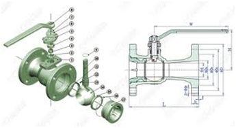
Parts of a Ball Valve
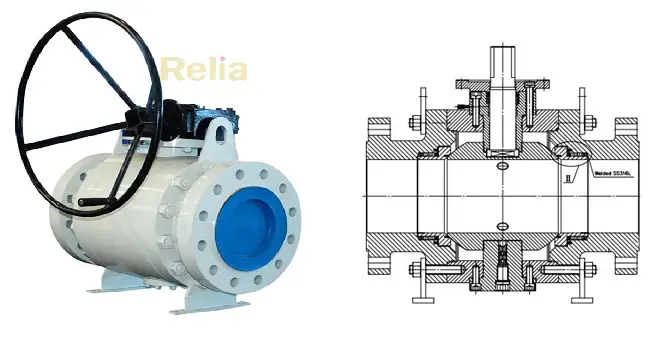
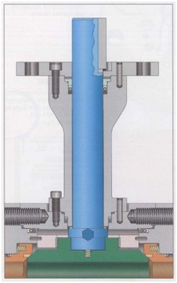
The housing, seats, ball, and lever for ball rotation are the major parts of a standard ball valve. Refer to Fig. 1 below which shows the internal parts of a ball valve.
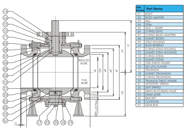
Ball valves are manufactured with the following crucial parts:
Valve Body:
The main part of a ball valve is the valve body which contains all of the internal components for on/off control.
Rotary Ball:
A ball with a center hole through which the media flows is the main characteristic of ball valves that differentiates these valves from other valve types. The hole of the ball through one axis connects the inlet to the outlet. The Stem controls the direction of the ball. The ball may be free-floating or trunnion-mounted. Trunnion-mounted ball valves reduce the operating torque to about 2/3rd that of the floating ball valves.
Stem:
The stem of a ball valve connects the ball to the external control mechanism.
Seats:
The seats of a ball valve are discs that lie in between the ball and the body. It provides the necessary seal between the two and also supports the ball.
Power Source:
A manual or actuated power source provides energy to the stem of the ball valve for rotating it. Manual actuation uses levers and handles, which the operator controls during requirements. Automatic actuators use electric, pneumatic, or hydraulic power sources.
Packing:
Packing is a seal around the stem to prevent the media escape.
Bonnet:
The bonnet is part of the ball valve body that contains the stem and packing.
The following video clearly shows the parts and working of ball valves using an animation.
Ball Valve Working Principle
A ball Valve is a rotary motion valve. When the stem (Item 04 in Fig. 1) transfers the motion to the connected ball (Item 03), the ball rotates. This ball of a ball valve is rested and supported by the ball valve seats (item 05). This rotation of the ball over valve seats allows the bore to open or close helping the fluid to flow or stop.
For manual ball valves with normal service, when the port opening of the ball is in line with the inlet and outlet ports, flow continues uninterrupted through the valve, undergoing a minimal pressure drop if a full-port ball is used. Obviously, the pressure drop increases with the use of a reduced-port ball. When the hand operator is placed parallel to the pipeline, the flow passages of the ball are in line with the flow passages of the body, allowing for full flow through the closure element. As the hand operator is turned to the closed position, the ball’s opening begins to move perpendicular to the flow stream with the edges of the port rotating through the seat. When the full quarter-turn is reached, the port is completely perpendicular to the flow stream, blocking the flow.
In throttling applications, where the ball is placed in a mid-turn position, the flow experiences a double pressure drop through the valve, similar to a plug valve. When a characterizable ball is used to provide a specific flow to position, as the ball is rotated from closed to open through the seat, a specific amount of port opening is exposed to the flow at a certain position, until 100 percent flow is reached at the full-open position.
As with all rotary-action valves, the ball valve strokes through a quarter-turn motion, with 0° as full-closed and 90° as full-open. The actuator can be built to provide this rotary motion, as is the case with a manual hand lever, or can transfer linear motion to rotary action using a linear actuator design with a transfer case.
When full-open, a full-port valve has minimal pressure loss and recovery as the flow moves through the valve. This is because the flow passageway is essentially the same diameter as the pipe inside diameter, and no restrictions, other than some geometrical variations at the orifices, are present to restrict the flow. The operation of throttling full-port valves should be understood as a two-stage pressure drop process. Because of the length of the bore through the ball, full-port valves have two orifices, one on the upstream side and the other on the downstream side. As the valve moves to a mid-stroke position, the flow moves through the first narrowed orifice, creating a pressure drop, and moves into the larger flow bore inside the ball where the pressure recovers to a certain extent. The flow then moves to the second orifice, where another pressure drop occurs, followed by another pressure recovery. This two-step process is beneficial in that lower process velocities are created by the dual pressure drops, which is important with slurry applications. The flow rate of a full-port valve is determined by the decreasing flow area of the ball’s hole as the valve moves through the quarter-turn motion, providing an inherent equal-percentage characteristic with a true circular opening. As the area of the flow passageway diminishes as the valve approaches closure, the sliding action of the ball against the seal creates a scissor-like shearing action. This action is ideal for slurries where long entrained fibers or particulates can be sheared off and separated at closing.
At the full-closed position, the entire face of the ball is fully exposed to the flow, as the flow hole is now perpendicular to the flow, preventing it from continuing past the ball.
With the characterized segmented ball design, only one pressure drop is taken through the valve—at the orifice where the seal and ball come in contact with each other. When the segmented ball is in the full-open position, the flow is restricted by the shape of the flow passageway. In essence, this creates a better throttling situation, since a pressure drop is taken through the reduction of flow area. As the segmented ball moves through the quarter-turn action, the shape of the V-notch or parabolic port changes with the stroke, providing the flow characteristic. Like the full-port design, the sliding seal of the characterizable ball provides a shearing action for separating slurries easily.
Ball Valve Types | Types of Ball Valves
Types of Ball valves are classified based on various parameters as listed below:
1. Ball Valve Types: Short Pattern vs. Long Pattern
Depending on the end-to-end dimension of the valves, two types of ball valves are available. They are
- Short pattern ball valves, and
- Long pattern ball valves
The end-to-end dimension and weight of short-pattern ball valves are less as compared to long-pattern ball valves. However, During piping design, a long pattern dimension is selected for ease of connection to pipe flanges. Also, short-pattern ball valves are not available after a specific size and flange rating. So, long pattern ball valves are the only option in such cases.
2. Types of Ball Valves: Soft Seated vs. Metal Seated
Depending on the seat materials of the valve, two types of ball valves are found; Soft Seated and Metal Seated Ball Valves.
Soft, non-metal seated ball valves satisfactorily cover most of the applications. Soft seated ball valves use a thermoplastic material such as PTFE, NBR, etc. However, abrasive media, high pressure, and temperature can severely stress the polymeric seals leading to damage. Because of this reason metal-seated ball valves were developed in the 1960s.
Metal seated ball valves use metal as seat material such as 316 SS, Monel, etc. Tight shut-off, no jamming, smooth control, good corrosion and wear resistance, wide temperature range, stability under pressure, etc. are the advantages that a metal-seated ball valve provides with its soft-seated counterparts.
The main differences between soft-seated and metal-seated ball valves are tabulated below:
| Soft Seated Ball Valve | Metal Seated Ball Valve |
| Elastic non-metallic material like PTFE, Delrin, Nylon, PEEK, etc | Metal Alloys like Copper alloy, Nickel alloy, Chrome Stainless Steel, etc are used as seat material |
| Used for low or medium temperature and pressure service | Widely used for high-pressure and temperature services |
| Low cost | High Cost |
| High level of Sealing | Comparatively poor sealing |
| Used for clean services like air, water, etc | Used for severe service conditions like hot water, oil, gas, acid, and other chemicals. |
| Lower torque requirement for operation. | Higher torque requirement |
Soft Seat Ball Valve Design
Thermoplastic or Elastomeric seats are inserted in a metallic holder (seat ring) to provide soft seating action in a ball valve. The main features of a soft-seated ball valve are
- Provide a good sealing ability.
- Lower in cost than metal seated valves.
- Limited temperature rating.
- Should not be used in dirty services, particularly on floating ball valves.
- Soft seat materials used are – PTFE, Nylon, Devlon, PEEK, etc.
- It is generally accepted a leakage of ISO 5208 Rate A
Metal Seat Ball Valve Design
The main features of metal-seated ball valves are
- Direct metal-to-metal contact between seat ring & ball.
- Ball Valves are used for abrasive service and for services where soft seated valves can not be used due to temperature limitations.
- The ball & seat contact surfaces are hard-faced to improve resistance to wear & prevent scratching caused by the solid particles contained in the process media.
- Metal sealing may be obtained by tungsten carbide coating (up to 200 deg. C), chromium carbide coating (above 200 deg. C), electroless nickel plating (ENP), or stellite hard facing.
- Acceptable leakage of ISO 5208 Rate D.
- Metal seats do not bed in as easily as soft seals under pressure. hence, ball and sealing rings to be precisely machined.
- Metal-seated ball valves are posed to pitting, fretting, stress corrosion cracking, and intercrystalline corrosion damages.
3. Ball Valves Types: Reduced bore, Full bore, V-shaped, and Vented ball valves
Based on the inner diameter of the ball valve two types of ball valves are used in industries; Reduced Bore Ball Valve and Full Bore Ball valve.
Reduced Bore (Reduced Port) Ball Valve Design
Reduced port ball valves are quite common in the piping industry. However, reduced bore ball valves introduce frictional losses. The main design features of such ball valves are
- The bore diameter is 1 size less than the pipe diameter for valve sizes up to 12” NB & 2 sizes less for 14” NB to 24” NB (and 3 sizes less for sizes above 24” NB).
- These ball valves are comparatively smaller in size with less weight.
- Have lower operating torque, resulting in a lower cost actuated valve package.
- Slightly higher pressure drop than full bore valve.
- Prevents pigging
- These valves are normally of a one-piece – end entry design for smaller sizes (up to 4”-150#) & two / three-piece – side entry design for bigger sizes.
- These valves are also called regular port valves.
Full Bore (Full Port) Ball Valve Design
Full bore or Full port valves do not cause extra frictional losses, and the system is mechanically easier to clean as it allows pigging.
- The bore inside diameter is the same as the pipe inside diameter.
- Very little pressure drop.
- Ball and housing are bigger.
- Of higher weight than reduced bore valve, hence more costly.
- Selected for specific process reasons, typically; minimum pressure drop, minimal erosion, pigging requirement, and gravity flow (to avoid liquid pocket)
V-shaped Ball Valves:
In V-shaped ball valves, The hole in the ball or the valve seat has a “V” shaped profile. This design offers more precise control of the flow rate.
Vented Ball Valves: In a vented ball valve design, a small hole is drilled into the upstream side to eliminate unwanted pressure within the valve.
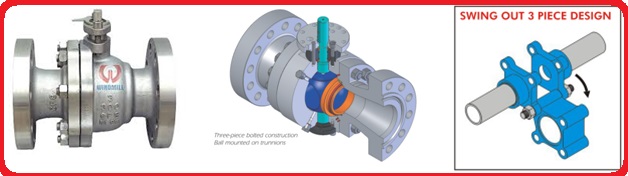
4. Types of Ball Valves: One-piece, Two-piece, and Three-piece ball valves
Depending on the body construction of valves, there are three types of ball valve designs; One-piece, Two-piece, and three-piece ball valves
Single Piece Body Design Ball Valves
In the single-piece design ball valve, the body will be cast/forged as one piece. The insertion of the ball will be through the end of the body and is held in position by the body insert. This design offers the unique advantage of eliminating the possibility of external leakage to the atmosphere through bolted body joints. This design restricts the ball valve to be of reduced port floating design only (for sizes up to 4” NB).
Two-piece / Three Piece Ball Valve Design
The two-piece design complements the single-piece design in sizes of 6” & above for reduced bore and for FB design valves. In a two-piece design, the body is constructed in two pieces and the ball is held in position by the body stud. There can be a full bore or reduced bore design possible in this construction.
In the case of a three-piece design, the body has two end pieces and one centerpiece. Three-piece design ball valves are most easily online maintainable. By removing the body bolts and keeping only one, the body can be swung away using the last bolt as the fulcrum, to carry out any installation or maintenance operation on the valve. This feature reduces maintenance downtime to a bare minimum.
For larger 2-piece or 3-piece ball valves, the dimensions between the body and flange should be checked so that sufficient clearance is available for bolting. During the vendor drawing review stage, the same should be checked and ensured.
5. Ball Valve Types: Side entry, Top entry, or welded body ball valves
From the perspective of Ball Valve Body Styles, they are divided into three types of ball valve designs. They are
- Side entry or end entry ball valves
- Top entry ball valves and
- Welded body ball valves
Side entry or end entry ball valve design
In the case of a side entry ball valve, the ball is assembled from the side part. They normally have two pieces or three pieces of the body. Each part of the body is assembled by a bolt/stud similar to joining a two-piece of flanges. Side entry ball valves are usually made by forging the metal. Each piece of the body is forged separately and then assembled together to get the complete design. This construction is robust in design and minimizes the defects caused by casting valves. Side entry ball valves are also easy to assemble and the trim component is also easy to align. Another advantage of the side entry ball valve type is that they are easily available from almost all vendors rather than a casting product that still needs some additional testing.
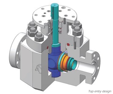
Top Entry Ball Valve Design
The main design features of top-entry ball valve types are
- Maintenance and repair of such ball valves are possible in-situ, by removing the top flange. This minimizes maintenance downtime.
- Limited space is required around the valve for maintenance.
- Available in welded as well as flanged end connections, but welded ends are preferred to reduce potential leak paths and minimize the ball valve weight.
- Heaviest and most expensive construction.
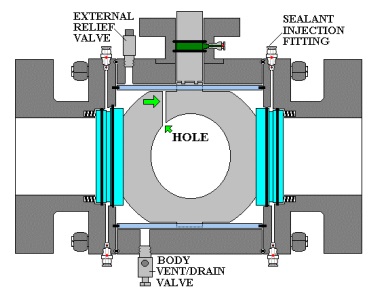
Welded Body Ball Valve Design
The main design features of this type of ball valve design are
- Welded body ball valve construction eliminates body flanges, reduces potential leak paths, and increases resistance to pipeline stresses.
- The minimum number of leak paths is hence beneficial in fugitive emission and vacuum applications.
- Compact and lightweight design
- The body draining & venting feature allows the ball valve maintenance technician to test each seat ring sealing ability with the ball in either the fully open or fully closed positions.
- Sealant injection fittings access directly to each seat ring. This enables the technician to top up the quantity of lubricant inside the valve sealant injection system on a periodic basis.
- Valve cleaner can also be injected into these fittings to flush out the old grease in the ball valve and to clean critical seal faces on the ball.
- Heavier sealants are also injected through the sealant injection fittings during an emergency when a critical seal is required.
- Applications – Oil & gas pipelines, compressor stations, measuring skids, etc.

6. Ball Valve Types depending on the type of ball design: Floating Ball Valve vs Trunnion Mounted Ball Valves
Depending on the supporting and positioning of the ball, two types of ball valves are used; Floating Ball Valves and Trunnion Mounted Ball Valves
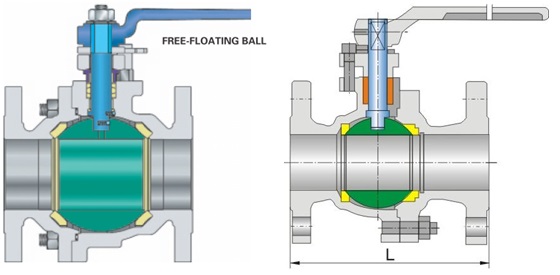
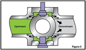
Floating or Seat Supported Ball Valve Design
In a floating ball valve, the ball is not fixed in place and is free to move slightly within the valve body. Sealing is achieved through the pressure of the fluid against the ball.
The major design features of a floating ball valve are
- Ball valve design in which the ball is not rigidly held on its rotational axis & is free to float between the seat rings.
- In the closed position, the ball is pushed against the seat by the pressure of the fluid from upstream and hence can pressure seal the downstream of the valve.
- Ball seats on the downstream seat only.
- Seat loading increases at a higher pressure and for larger sizes and becomes excessive, for the soft seated valve. Also, the higher the size the heavier the ball, and the less likely it is to be moved by pressure. Hence the need for a trunnion-mounted ball valve design comes into the picture.
- Floating design ball valves have lower manufacturing costs.
- Valves of small sizes and lower pressure ratings are seats supported (10” for 150#, 6” for 300# & 2” for 600# & above).
- The seat-supported design generally needs higher operating torque.
- Metal seated floating ball valves also incorporate spring-loaded seats.
Trunnion Mounted Ball Valve
Trunnion ball valves have a fixed ball with a shaft extending through it. This design provides more support to the ball, making it suitable for high-pressure and large-diameter applications. Trunnion ball valves are known for their increased durability and reliability in demanding conditions.
The major design characteristics of a trunnion-mounted ball valve are
- The ball is fixed in position by the stem & the trunnion which are supported by bearings in the body.
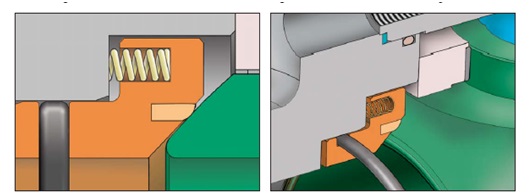
- The seat is spring-loaded onto the ball, giving reliable sealing at low pressures.
- The key feature of this ball valve is that the ball does not shift as it does in a floating valve to press the ball into the downstream seat. Instead, the line pressure forces the upstream seat onto the ball to cause it to seal.
- As the area on which the pressure acts is much lower, the amount of force exerted on the ball is much less, leading to lower friction values and smaller actuators or gearboxes.
- Seat designs are either single or double-piston effects.
- Valves of larger sizes and higher pressure ratings are trunnions mounted.
- All standard trunnion-mounted ball valves shall be provided with self-relieving seats allowing automatic body cavity relief exceeding 1.33 times the valve pressure rating at 38°C (overpressure due to thermal expansion of trapped fluid).
7. Types of Ball valves: Single vs. Double piston effect design
Based on the pressure relieving capability of the ball valve seats, two types of ball valves are designed; Single Piston Effect Design and Double Piston Effect Ball Valve Design
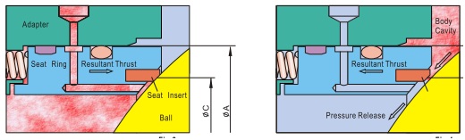
Single Piston Effect Seat Design
The important design features of single piston effect seat design are
- Seats of the ball valves are pressed on the ball by means of spring load.
- As the body cavity pressure increases than the spring load, the seats are pushed back and the pressure is released in the line. This is called a single-piston effect (the pressure in the body cavity is the only acting parameter)
- Cavity relief to the downstream side, if both the ball valve seats are of single-piston effect design.
- Each seat is self-relieving the body cavity overpressure to the line.
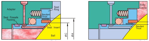
Double Piston Effect Seat Design
The design characteristics of a double piston effect seat design ball valves are
- In this seat design, the medium pressure, as well as body cavity pressure, creates a resultant thrust that pushes the seat rings against the ball. This is called a double piston effect (the pressure in the pipe & that in the body cavity, both are acting parameters)
- Ball Valves with this design require a cavity pressure relief device to reduce the body cavity pressure.
- DPE is synonymous with “bi-directional”, and SPE is synonymous with “uni-directional” as defined by API 6D/ISO 14313.
The working of Single Pistion Effect and Double Piston Effect Design is clearly shown in the following video:
Body Cavity Relief (Pressure Equalisation)
- Ball valves are double-seated valves that incorporate a cavity between the seats.
- The body cavity will get pressurized only when the seats are damaged.
- Cavity relief provision is required only for trunnion-mounted ball valves. Not required for floating ball valves as the seats are fixed & the ball is floating.
- Where possible, cavity relief shall be to the upstream side of the valve.
DPE – External pressure relief
- When the body cavity pressure increases above the net spring load of the pressure relief valve, the cavity pressure is vented through the Pressure Relief Valve.
- The Relief Valve outlet line can be vented to the atmosphere / connected to the vent system or back to the upstream piping.
Combination Seats
- In some cases, a single-piston effect seat is used for the upstream side and a double-piston effect seat is used for the downstream side.
- This enables the cavity overpressure to release to the valve upstream side and also doesn’t require an external relief valve.
- These ball valves are unidirectional and the flow direction is clearly marked on the valve body.
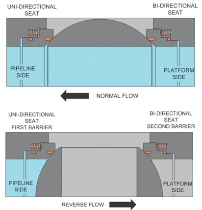
Ball valve Seat Design for Export Line
- This seat configuration gives a single barrier against normal flow conditions and a double barrier against reverse flow coming from the downstream pipeline.
- For the ESD/PSD valve, a reverse configuration is required than that shown here. ESD valves require SPE for the upstream seat and DPE for the downstream seat.
Pressure Temperature Ratings of Ball Valves
The pressure-temperature ratings of ball valves are decided based on the valve body and sealing materials used for soft-seated ball valves. Sealing materials may be PTFE, 15 to 25% glass-filled PTFE, FPM, NRG, Celastic, POM, Lyton, and Steel. It is very difficult to pre-determine exact pressure-temperature ratings for all kinds of media under all imaginable loading conditions.
The pressure-temperature rating for metal-seated ball valves is decided based on body ratings.
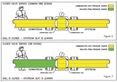
Double Block & Bleed (DBB) feature
When the ball valve is in a fully closed or fully open position, each seat seals off the process medium independently at the same time between the up/downstream and body cavity; it allows bleeding of the cavity pressure through a drain or vent valve. This DBB feature permits in-line periodic inspection of the valves and the checking of sealing integrity when the valve is installed in the line. This feature is available with self relieving seat (SPE) configuration.
DBB Vs DIB
- If a ball valve has both seats as unidirectional (SPE) seats, it is called a Double Block & Bleed (DBB).
- If a ball valve has one or both bidirectional (DPE) seats, it is called a Double Isolation & Bleed (DIB).
- In the DBB valve, the downstream seat pushes away from the valve once the body cavity pressure is higher than the downstream pressure, allowing fluid to flow downstream past the closed valve. In the DIB valve the downstream seat seals and prevents the upstream pressure from reaching the downstream piping.
A clear animation of the DBB vs DIB philosophy is presented in the following animation:
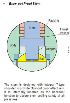
Blow-Out Proof Stem Design Feature of Ball Valve
- When the ball valve is in the open/closed position, the pressure is always acting upon the bottom of the stem, trying to push the stem up.
- The stem is sealed by o-rings and graphite packing rings.
- The stem is held in position by the stem housing, which is bolted to the body.
- The graphite packing rings are compressed and held in position by the gland flange, which is bolted to the stem housing.
- Therefore, when the gland flange is removed to replace the graphite packing rings, the stem is still held securely, by the stem housing.
- That means the blow-out-proof stem feature ensures that the top graphite packing rings can be replaced while the valve is under pressure, without the stem being pushed out (blown out).
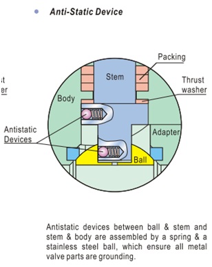
Anti-Static Design Feature of Ball Valves
- The build-up of static electricity can occur as a result of the constant rubbing of the ball against the PTFE seats. This can be a potential fire hazard, especially while handling flammable fluids.
- In the anti-static feature, spring-loaded balls are provided between the ball & stem and stem & body which provides electrical continuity.
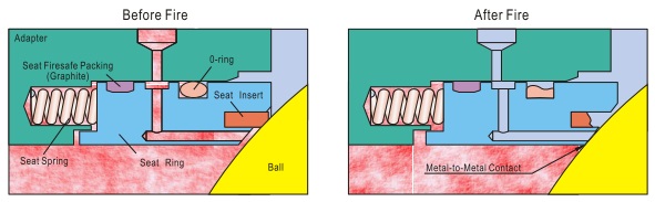
Fire Safe Design of Ball Valves
1) Internal Leakage Prevention (from the pipeline to the body cavity)
- When non-metal resilient seats are destroyed in a fire, the upstream medium pressure pushes the ball into the downstream metal seat lip to cut off the line fluid and prevent internal leakage due to secondary metal-to-metal seals.
- Another fire-safe packing is provided at the seat ring for internal leakage prevention to the body cavity.
- Graphite is normally used as a fire-safe packing material because the melting point of graphite is 1000 degrees C.
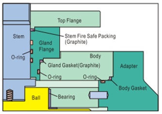
2) External leakage prevention (from body/stem joints to atmosphere)
- All the possible external leakage points between the stem & gland flange, gland flange & body, and body & adapter are sealed with a primary O-ring and then a secondary graphite gasket. When the fire burns out the primary O-ring seal, the secondary graphite gasket seal can prevent the process medium from external leakage.
- Fire-safe seals are generally not designed for fugitive emission performance (fugitive emission – emissions of gases or vapors from pressurized equipment due to leaks).
- The fire testing of valves is carried out as per API 6FA, API 607, ISO 10497, or BS 6755 Part II.
Fire Safe vs. Fire Tested Design
- Fire-safe design is a design that by the nature of its features and materials is capable of passing a fire test.
- It is capable of passing a fire test with specified limits on leakage to the atmosphere and downstream after being closed subsequent to fire exposure.
- A fire-tested design is a design subjected successfully to fire testing as per the applicable testing standard.
- That means the fire-safe valves are not necessarily fire-tested by the manufacturer.
Ball Valve Fire Testing Criteria
- One test valve may be used to qualify valves larger than the test valve, not exceeding twice the size of the test valve.
- A 16” size valve will qualify all larger sizes.
- One test valve may be used to qualify valves with higher pressure ratings but no greater than twice the pressure rating of the test valve.
- The above criteria are acceptable for valves of the same basic design as the test valve & the same non-metallic materials.
Ball valve Sealant Injection System
- Ball Valves are to be equipped with sealant & lubricant injection connections located at the stem and seat area if specified by the purchaser.
- The valve design & material selection should negate the need for such a connection.
- If specified, this injection connection is integrated with a check valve to provide backup sealing, Also a check valve is equipped at the front of seat sealant injection to avoid blowing out in case of the wrong operation.
- When the soft sealing materials (seat inserts and o-rings) are damaged and leakage happens by fire or other accident, the sealant can be injected through the injection fittings.
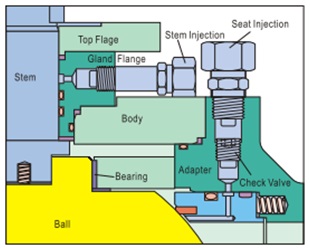
- The sealant injection system through the seat up to the ball contact circle may provide temporary sealing until it is possible to restore the primary seal.
- No seat sealant injection shall be provided for ESD valves.
Extended Bonnet Ball Valve
The integrity of stem seals at very low temperatures (-30 degrees C & below) is the major hurdle that must be overcome. Specially designed extended bonnets installed to valves offer a safe & efficient method to accomplish stem seal integrity.
The bonnet extension provides a gas column that allows the gas to vaporize from contact with the warm ambient temperature outside the service line. This vapor column insulates the stem seal and maintains the seal integrity. Bonnet extension also helps with thermal insulation installation.
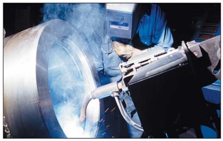
Weld Overlay
Sealing areas & other wetted parts of the ball valve can be cladded in case of corrosive service. More frequently used materials for the overlay process are stainless steel, DSS & high nickel alloys. This technology is cost-effective for ball valves in highly corrosive or erosive services. Considerable cost saving without sacrifice to service life or performance. It can be done cost-effectively for sizes 8” and larger. Welding is performed in accordance with ASME BPV section 9.
Ball Valve Seat Insert Materials
Thermoplastic seat/seal inserts
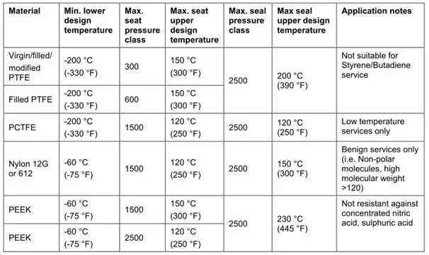
Devlon V: Temp. Range -100 deg. C to 150 deg. C
Elastomeric seat/seal inserts
- Zero leakage is easier obtained by softer seals (elastomeric), while the resistance to scratches and other factors (temperature, pressure, erosion) is obtained by harder seals (thermoplastic).
- PTFE is generally not recommended for high pressure (cl. 900 & higher) while it is suitable for a wide range of temperatures and resistant to many fluids.
- Nylon 12G is more suitable than PTFE for higher pressure but has a limited range in temperature.
- Nylon 6 should not be used as it absorbs humidity.
- Devlon V is similar to Nylon 12G but with a wider range of temperature applications (lower & higher)
- PEEK is recommended for high temperatures (up to 260 deg.C) but it is very hard compared to other nonmetallic materials.
- Kel-F is especially recommended for cryogenic service.
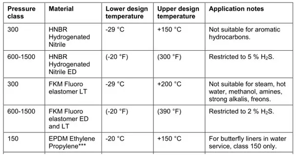
O-Rings (Elastomeric)
O-rings are used for below applications:
- Stem seals
- Seals between seat and body/closure
- Seals between body and bonnet/closure
Materials are generally as follows:
- Viton (fluor elastomer)
- NBR (nitrile butadiene rubber)
- HNBR
O-rings are not allowed in the seat ring-body joint as well as for the body-bonnet joint. The ball valve seat ring shall have a primary lip seal with a fire-safe graphite ring.
On the stem side, if the seal material specified in the requisition as thermoplastic, it shall be of lip seal type with Inconel 718 spring. If the seal material is specified as elastomeric, it shall be of AED type.
Lip Seal
- For applications where elastomeric O-rings are not reliable, lip seals are used (for body & stem sealing).
- Lip seals are self-energized seal systems, made of a Teflon cover and a spring (Inconel 718 material).
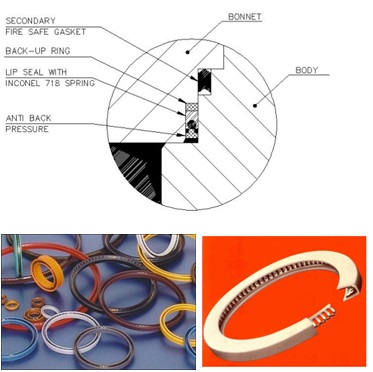
- The spring provides the initial load (due to the low elasticity of Teflon), while the fluid pressure provides the load to force the lips on the sealing surfaces.
- Lip seal housing on CS valves shall be SS316 weld overlayed (3mm thick)
Ball Valve End Connections
The type of ball valve ends are as follows:
- Flanged ends with raised face or ring joint face
- Threaded ends
- Socket weld ends
- Butt-weld ends – Soft, as well as metal seated butt-welding end valves, shall be provided with butt-weld pup pieces.
- This avoids damage to the ball valve seat as well as soft seal materials due to welding heat.
- The pup piece length shall be
- 200mm for sizes up to 2” NB,
- 400mm for up to 12” NB size &
- 800mm above 12” NB sizes
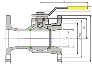
Ball Valve Operator
Ball Valves can be operated by a lever, wrench, or hand wheel or they can be pneumatic, hydraulic, or motor-operated. A ball valve is rotated in a clockwise direction to close & anti-clockwise direction to open. The maximum lever length shall not exceed 450 mm & maximum handwheel diameter shall not exceed the valve face-to-face dimension of 800mm whichever is smaller. A gear operator is required to be provided for valves as per the below criteria:
- 6” & larger for class 150 ball valves
- 4” & larger for class 300 & 600 and
- 3” & larger for class 900 onwards
Ball Valves as ESD Valve
Ball valves as ESD valve application shall be of trunnion mounted type with metal seat design. The minimum size shall be 2” NB. Upstream seats of such ball valves shall be with a single-piston effect and downstream seats with a double-piston effect.
The SPE & DPE shall be marked permanently on the respective seat side and the flow arrow shall be embedded on the ball valve body. However, the valve shall be suitable for bi-directional isolation. The seat ring shall have 2 primary leap seals with a fire-safe graphite ring. The stem shall have a minimum of 2 primary lip seals or U or V-shaped packing with fire-safe secondary seals.
Grease injection fitting shall be provided between primary & secondary seals on the stem side with 2 in-built check valves. No seat sealant injection shall be provided for ESD valves.
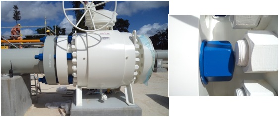
Ball Valve Lifting & Supporting Provision
Ball Valves of sizes 8” NB and above or 250 Kg & heavier shall be equipped with lifting lugs. Tapped holes & eye bolts are not acceptable. Ball valves weighing more than 750 kg shall have support lugs and these should be designed to take care of the vertical & lateral loads of valves. The support height shall be as minimum as possible.
Other Requirements of Ball Valves
Drain and vent connections of Ball Valves
Drain and Vent connections shall be drilled & threaded for ball valves up to 900# pressure class & for sizes less than 6” –FB & 8”-RB. The connections shall be fitted with a threaded plug. The plug shall be suitably locked by a locking ring to prevent loosening.
The drain & vent connections for ball valves above 900# pressure class & 6” –FB / 8” -RB & above sizes shall be fully welded flanged type, fitted with a blind flange. If drain/vent/sealant injection is asked, ensure the orientation of the connections is accessible at the site. During the ball valve vendor drawing review, the same should be checked.
Ball Valve Specification
While purchasing a ball valve, the following information should be provided to the vendor/manufacturer:
- Ball Valve Size and Pressure Class Rating
- Type of the Ball: Floating or Trunnion mounted design
- The pattern of the ball valve: standard or short
- Bore type: full or reduced bore
- Ball Valve End Connection type.
- The requirement of drain connection.
- The requirement of the Sealant Injection system.
- The need for a Locking device
- The requirement of Valve support – if any
- Anti-Static device
- Operator Details: Lever/Gear/ Actuator (Electric, Pneumatic, or Hydraulic Operated)
- The material Valve Body, Seat Rings, Trunnion, Trim, Seals, Gaskets, Bolts, Nuts, and Packing material
- Seating Type: Soft or Metal Seated
- Valve orientation
- Specific Certification requirements
- The requirement for a Fire-safe test
- Applicable Painting details
- The requirement of an Integral bypass connection
- The requirement of Lugs or Lifting arrangements.
Advantages of Ball Valves
The important Advantages of a Ball valve are listed below
- Quarter turn straight thru valve / fast opening & closing
- Tight Shut off as well as very easy to use
- Application as isolation valve (on and off condition)
- Suitable for Emergency shutdown conditions
- Multi-design flexibility
- Compact, economical designs
- Suitable for high-pressure service conditions.
- Long service life.
- Suitable for a range of industrial applications.
- Low maintenance
Because of all these benefits, ball valves find wide application in the following industries.
- Oil & Gas, Chemical, Petrochemical, Refinery
- Food & Beverage Equipment
- Vehicle Wash Systems
- Automotive
- Home Appliances
- Power Processing
- Manufacturing Facilities
- Pharmaceutical
- Irrigation & Water Treatment Equipment
- Chemical Admixtures & Treatment
Disadvantages of Ball Valves
However, there are a few disadvantages of ball valves like
- Not suitable for throttling
- Fluid trapped in the body cavity
- Limited working temperature range
Ball Valve vs. Gate Valve
The major differences between a Ball Valve and a Gate valve are tabulated below:
| Ball Valve | Gate Valve |
| Ball Valve uses a ball for opening or closing | Gate valve uses a gate or wedge for opening or closing |
| The ball Valve is a quarter-turn rotary motion valve | A gate valve uses a gate or wedge for opening or closing |
| The sealing capacity of Ball Valves is comparatively higher | Comparatively less sealing. |
| Durability more | Less durability |
| Quick operation, prone to surge | Operation is slow hence, less probability of surge creation. |
| More number of valve configurations | Less number of valve configurations |
| More expensive | Comparatively low cost |
| Less Corrosion | Higher Corrosion |
| Low-Pressure Drop | High-Pressure Drop |
In the realm of fluid control, ball valves stand as a testament to the ingenuity of engineering. Their versatile design, reliable operation, and ability to withstand challenging conditions make them an indispensable component across industries. Whether in oil and gas pipelines, chemical plants, or everyday household systems, the unassuming ball valve plays a crucial role in ensuring the smooth and efficient flow of fluids that power our modern world.
Frequently Asked Questions
What is a ball valve, and how does it work?
A ball valve is a type of valve used to control the flow of fluids. It operates by rotating a spherical ball inside the valve body. When the hole in the ball aligns with the flow direction, the valve is open, allowing fluid to pass through. Rotating the ball to block the hole closes the valve, stopping the flow.
What are the main types of ball valves?
There are two primary types of ball valves:
- Floating Ball Valves: The ball in these valves is not fixed in place and relies on fluid pressure to create a seal.
- Trunnion Ball Valves: These valves have a fixed ball with a shaft extending through it, providing additional support and reliability, especially in high-pressure applications.
Where are ball valves commonly used?
Ball valves are widely used across various industries, including:
- Oil and Gas
- Water Treatment
- Chemical Processing
- HVAC Systems
- Manufacturing
- Agriculture
- Residential Plumbing
What are the advantages of using ball valves?
Some key advantages of ball valves include:
- Quick and reliable operation
- Minimal pressure drop
- Versatility in handling different fluids, temperatures, and pressures
- Low maintenance requirements
- Tight sealing to prevent leaks
Can ball valves be used for both on/off and throttling applications?
Yes, ball valves are suitable for both on/off and throttling (partial flow control) applications. However, for precise control in throttling situations, it’s important to choose the right type of ball valve and size it appropriately.
Are ball valves suitable for high-pressure applications?
Trunnion ball valves, with their fixed ball and additional support, are well-suited for high-pressure applications. Floating ball valves are generally used in lower-pressure situations.
Are ball valves suitable for controlling slurries and solid-laden fluids?
While ball valves can handle some solid-laden fluids, they are not the best choice for controlling highly abrasive or viscous slurries. In such cases, specialized valves like knife gate valves or pinch valves may be more appropriate.
Can ball valves be automated for remote control and monitoring?
Yes, ball valves can be equipped with actuators (electric, pneumatic, or hydraulic) for remote control and automation. This is especially useful in industrial processes where precise control and monitoring are essential.
How do I select the right ball valve for my application?
To select the right ball valve, consider factors like the type of fluid, operating temperature and pressure, pipe size, the specific application, end connections, material requirements, flow control requirements, actuation types, etc
Few more useful Resources for you..
Guidelines for the selection of normal valve type
Details about control valves
A brief article on Valve Inspection & Testing
An article on ROTARY SELECTOR VALVE (RSV) and MULTIPHASE FLOW METER (MPFM)
Routing Of Flare And Relief Valve Piping: An article-Part 1
A short presentation on Control Valve Sizing
Basics of Piping Design and Layout
Piping Stress Analysis Basics
Piping Materials Basics
We are one of the leading manufacturers of watersupply pipeline VALVES . Interested in manufacturing Metal bellow (Expansion joint)
“Ball Valve Design Features” very informative, really enjoyed reading.
Right
thanks a lot, that’s the best consolidated description of a ball valve design that i have seen anywhere on internet
Please tell me solution for Ball valve which are allowing fluid passing(Leakage) very soon after installation.Using following material for parts:
Ball -ASTM A217 grade CA15
seat – PEEK
O-rings – Viton AED
spring – Inconel X750
Process Fluid – Crude Oil petrolium
and some rubbing like things also happening in gear box as well.
Value added information. Thanks a lot.
Hi there
Great blog. it’s very informative and helpful. you give knowledge about the ball valve. very good define. thanks for sharing with us. well done. keep sharing.
Very informative
Very informative and helpful.
Excellent presentation!